



How to Replace the Rear Door Lock Actuator on a 2014-2019 Toyota Highlander
Step-by-step DIY guide with tools, parts, safety tips, and latch torque specs for 2014, 2015, 2016, 2017, 2018, 2019
How to Replace the Rear Door Lock Actuator on a 2014-2019 Toyota Highlander
Step-by-step DIY guide with tools, parts, safety tips, and latch torque specs for 2014, 2015, 2016, 2017, 2018, 2019


🔧 Highlander - Rear Door Lock Actuator Replacement
This repair replaces the rear door lock actuator inside the rear door. The actuator is the small electric latch motor that locks and unlocks the door when you use the key fob, switch, or smart lock system.
On your Highlander, the rear door trim panel, moisture barrier, lock rods/cables, and latch/actuator assembly need to be removed carefully so the new actuator can be installed without damaging clips or wiring.
Difficulty Level: Intermediate | Estimated Time: 1.5-2.5 hours
⚠️ Safety & Precautions
- ⚠️ Disconnect the negative battery cable before unplugging door electrical connectors to prevent shorts.
- ⚠️ Keep the window fully raised before starting so the glass does not interfere with the latch area.
- ⚠️ Door trim clips can break easily. Use plastic trim tools, not metal screwdrivers, on painted or visible panels.
- ⚠️ The moisture barrier must be resealed. It keeps water from entering the cabin.
- ⚠️ Wear cut-resistant gloves. The inside of the door shell has sharp stamped-metal edges.
🔧 Required Tools
You'll need the following tools for this repair:
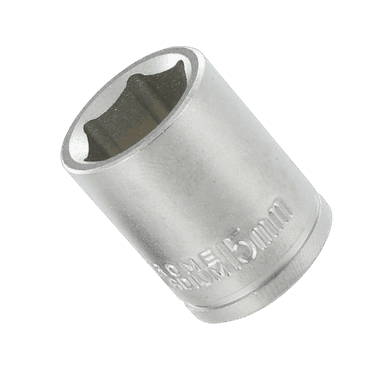
- 10mm socket
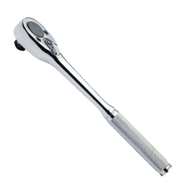
- Ratchet with 3/8-inch drive
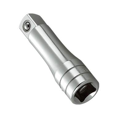
- 3-inch extension with 3/8-inch drive
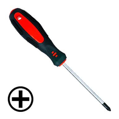
- Phillips #2 screwdriver
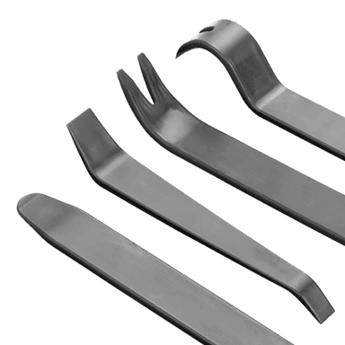
- Plastic trim removal tool set
- Small flat-blade screwdriver
- Torx T30 socket
- Needle-nose pliers
- Panel clip removal pliers
- Butyl tape roller
- Pick tool set
- Painter’s tape
- Work light
- Torque wrench, inch-pound range
- Safety glasses
- Cut-resistant gloves
🔩 Required Parts
HowToo sells all the parts you need for this repair:
- Rear door lock actuator/latch assembly - Qty: 1
- Rear door trim panel clips - Qty: 6-10
- Butyl sealing tape - Qty: 1 roll
📋 Before You Begin
- Park your Highlander on level ground and set the parking brake.
- Raise the rear door window fully before disconnecting the battery.
- Open the rear door you are repairing and make sure it stays open securely.
- Use painter’s tape around the door handle trim and switch trim to help prevent scratches.
- Disconnect the negative battery cable using a 10mm socket. Wait 90 seconds before unplugging door connectors.
- A trim tool is a plastic prying tool made to pop panels loose without scratching them.
- Butyl tape is sticky black sealing tape used to reseal the plastic moisture barrier inside the door.
🔨 Step-by-Step Instructions
Follow these steps in order:
Step 1: Disconnect the Battery
- Use a 10mm socket and ratchet to loosen the negative battery terminal clamp.
- Lift the negative cable off the battery post and move it aside so it cannot spring back.
- Wait at least 90 seconds before working on door electrical connectors.
- Take a phone photo first.
Step 2: Remove the Rear Door Switch Panel
- Use a plastic trim removal tool to gently pry up the rear window switch panel from the armrest.
- Lift the panel slowly. Do not pull hard because the wiring connector is still attached.
- Use a small flat-blade screwdriver to press the connector lock tab, then unplug the switch connector.
- Set the switch panel somewhere safe.
Step 3: Remove Hidden Door Panel Screws
- Use a plastic trim removal tool to open or remove the small screw cover behind the interior door handle.
- Use a Phillips #2 screwdriver to remove the screw behind the interior handle.
- Use a Phillips #2 screwdriver to remove the screw in the armrest/switch panel opening.
- Place the screws in a cup so they do not get lost.
Step 4: Release the Door Trim Panel Clips
- Use panel clip removal pliers or a plastic trim removal tool at the lower edge of the door panel.
- Pop the clips loose one at a time around the bottom and sides of the panel.
- Once the clips are loose, lift the whole door panel straight upward to unhook it from the window ledge.
- Do not yank the panel away yet. Cables may still be connected.
Step 5: Disconnect Handle Cables and Courtesy Wiring
- Support the door panel with one hand.
- Use needle-nose pliers or your fingers to unclip the interior handle cable ends from the handle bracket.
- Use a small flat-blade screwdriver to unlock any remaining courtesy light or speaker connector tabs, then unplug them.
- Set the door trim panel on a clean towel to avoid scratching it.
Step 6: Peel Back the Moisture Barrier
- Use a plastic trim removal tool to gently separate the plastic moisture barrier from the black butyl sealant.
- Peel back only enough of the rear section to access the latch and actuator area.
- Use a pick tool if the butyl stretches, but do not tear the plastic barrier.
- Warm butyl peels easier.
Step 7: Disconnect the Actuator Electrical Connector
- Use a work light to look inside the rear edge of the door.
- Find the electrical connector going to the door latch/actuator assembly.
- Use a small flat-blade screwdriver to press the connector lock tab, then unplug the connector.
- Check that the connector terminals are not green, burned, loose, or wet.
Step 8: Disconnect Lock Rods or Cables
- Use a work light to identify the rods or cables connected to the latch assembly.
- Use needle-nose pliers to rotate the plastic retaining clips off the metal rods.
- Lift the rods out of the latch levers carefully.
- If equipped with cable-style retainers, use a small flat-blade screwdriver to release the cable housing from its bracket.
- Take a photo before removing each rod or cable so reassembly is easier.
Step 9: Remove the Rear Door Latch/Actuator Assembly
- At the rear edge of the door, use a Torx T30 socket with ratchet to remove the three latch mounting screws.
- Hold the latch assembly from inside the door while removing the last screw so it does not fall.
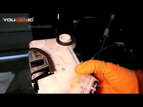
- Guide the latch/actuator assembly out through the access opening in the door.
- If the assembly catches, use a work light and gently reposition the rods/cables. Do not force it.
Step 10: Transfer Any Brackets or Rod Clips
- Compare the old and new rear door lock actuator/latch assembly side by side.
- Use a Phillips #2 screwdriver, Torx T30 socket, small flat-blade screwdriver, or needle-nose pliers to transfer any reusable brackets, rod clips, or rubber bumpers if your replacement part does not include them.
- Make sure all levers on the new part move the same way as the original.
Step 11: Install the New Actuator/Latch Assembly
- Guide the new rear door lock actuator/latch assembly into the door through the access opening.
- Align it with the three screw holes at the rear edge of the door.
- Start the three latch screws by hand first to prevent cross-threading.
- Use a Torx T30 socket and torque wrench to tighten the latch screws to Torque to 5.5 Nm (49 in-lbs).
Step 12: Reconnect Rods, Cables, and Electrical Connector
- Use needle-nose pliers to place each lock rod back into the correct latch lever.
- Snap each plastic rod retaining clip fully closed by hand.
- If equipped with cable retainers, push each cable housing back into its bracket until it clicks.
- Plug in the actuator electrical connector by hand until the lock tab clicks.
- Use your phone photo to verify all rods and cables are routed the same way as before.
Step 13: Test Before Reinstalling the Door Panel
- Keep hands and tools clear of the latch.
- Temporarily reconnect the negative battery cable using a 10mm socket.
- Use the key fob and interior lock switch to test lock and unlock operation.
- Use a screwdriver shaft to gently close the latch claw, then pull the exterior and interior handles to confirm it releases.
- Use a 10mm socket to disconnect the negative battery cable again before final reassembly.
Step 14: Reseal the Moisture Barrier
- Press the moisture barrier back into the original butyl seal by hand.
- Use a butyl tape roller to smooth the seal all the way around the opening.
- Add new butyl sealing tape where the old seal is missing, stretched, or no longer sticky.
- Make sure wiring passes through the correct openings and is not pinched.
Step 15: Reinstall the Rear Door Trim Panel
- Reconnect the interior handle cables by hand and confirm each cable end is seated in its lever.
- Reconnect any courtesy light or speaker connectors by hand until they click.
- Hang the top of the door panel over the window ledge.
- Align the door panel clips with the door holes.
- Press firmly around the sides and bottom of the panel by hand to seat each clip.
Step 16: Reinstall Screws and Switch Panel
- Use a Phillips #2 screwdriver to reinstall the screw behind the interior door handle.
- Use a Phillips #2 screwdriver to reinstall the screw in the armrest/switch panel opening.
- Snap the screw cover back into place by hand.
- Plug the rear window switch connector back in by hand until it clicks.
- Press the switch panel back into the armrest until it sits flush.
Step 17: Reconnect the Battery
- Place the negative battery cable back onto the battery post.
- Use a 10mm socket and ratchet to tighten the terminal snugly.
- Do not overtighten the terminal clamp. It only needs to be secure and unable to rotate by hand.
✅ After Repair
- ✅ Lock and unlock the repaired rear door with the key fob several times.
- ✅ Test the driver master lock switch and the rear door lock knob.
- ✅ Open the door from the outside handle and inside handle to confirm both release correctly.
- ✅ Test the rear window switch. If auto window operation is not normal, initialize it by holding the switch down until fully open, then holding it up until fully closed for a few seconds.
- ✅ Spray water around the outside of the door glass area and check inside for leaks if the moisture barrier was heavily disturbed.
- ✅ Listen for rattles while driving. A rattle usually means a loose rod clip, cable, or trim clip.
💰 DIY vs Shop Cost
Shop Cost: $325-$575 (parts + labor)
DIY Cost: $80-$225 (parts only)
You Save: $245-$350 by doing it yourself!
Shop labor rates vary but typically run $100-$150/hour. This repair takes a shop approximately 1.0-1.8 hours.
🎯 Ready to get started?
HowToo makes it easy: same-day/2-day shipping on every part, plus all the tools and specialty tools you need! Check out the parts and tools sections below to add everything to your cart.