




How to Replace the MAF Sensor on a 2016-2025 Chevrolet Malibu 1.5L Turbo (Trim: LS | Engine: Inline 4 1.5L)
Step-by-step instructions with required tools, parts, torque specs, and safety tips for 2016, 2017, 2018, 2019, 2020, 2021
How to Replace the MAF Sensor on a 2016-2025 Chevrolet Malibu 1.5L Turbo (Trim: LS | Engine: Inline 4 1.5L)
Step-by-step instructions with required tools, parts, torque specs, and safety tips for 2016, 2017, 2018, 2019, 2020, 2021


🔧 Malibu - Mass Air Flow Sensor Replacement
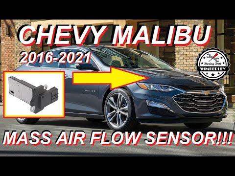
The mass air flow (MAF) sensor measures how much air enters your Malibu’s 1.5L turbo engine. Replacement involves unplugging the electrical connector, removing two small screws, and installing the new sensor without touching its delicate sensing element.
Difficulty Level: Beginner | Estimated Time: 20-30 minutes
Assumption: The factory air-intake system is installed.
⚠️ Safety & Precautions
- ⚠️ Let the engine cool completely before working near the turbocharger and intake plumbing.
- 🛑 Switch the ignition off and keep the key away from the vehicle.
- 🔌 Battery disconnection is not required, but the ignition must remain off while the sensor is unplugged.
- 🚫 Never touch the new sensor’s wires or electronic sensing element.
- 💧 Do not use cleaner, compressed air, or shop towels on the new sensor.
🔧 Required Tools
You'll need the following tools for this repair:
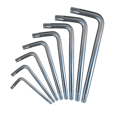
- Torx T20 screwdriver
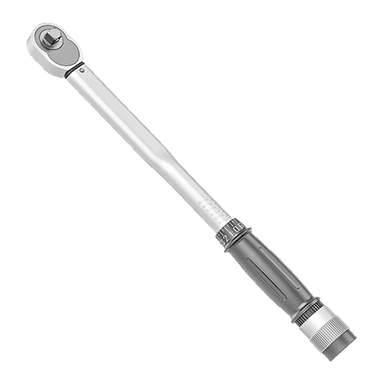
- 1-5 Nm torque screwdriver with Torx T20 bit
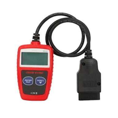
- OBD-II scan tool
- Nitrile mechanic gloves
- Safety glasses
🔩 Required Parts
HowToo sells all the parts you need for this repair:
- Mass air flow sensor for 1.5L turbo engine - Qty: 1
- MAF sensor sealing O-ring - Qty: 1, if not included with sensor
📋 Before You Begin
- 🚗 Park your Malibu on level ground, select Park, and apply the parking brake.
- 🌡️ Shut off the engine and allow the engine compartment to cool.
- 🔑 Turn off all electrical accessories and move the key or transmitter away from the vehicle.
- 📍 Open the hood. Locate the MAF sensor on the air-cleaner outlet duct, immediately downstream from the air-filter housing.
- 🧰 A Torx driver has a six-point, star-shaped tip that fits the sensor’s retaining screws.
🔨 Step-by-Step Instructions
Follow these steps in order:
Step 1: Locate and Inspect the Sensor
- Wear the safety glasses and nitrile mechanic gloves.
- Follow the large intake duct from the air-filter housing toward the engine. The MAF sensor is the small electrical sensor mounted in that duct.
- Confirm that the ignition is off before touching its connector.
Step 2: Disconnect the Electrical Connector
- Press the connector’s locking tab with your fingers, then pull the connector straight away from the sensor.
- Pull on the connector body, not the wires.
- If the connector has a secondary colored lock, slide that lock back with your fingernail before pressing the release tab.
- Inspect the terminals for moisture, corrosion, bent pins, or damaged wiring.
- Never force a stubborn connector.
Step 3: Remove the Old MAF Sensor
- Use the Torx T20 screwdriver to remove the two sensor retaining screws.
- Set the screws aside where they cannot fall into the engine compartment.
- Lift the sensor straight out of the intake duct. Gently rock its plastic housing if the sealing O-ring is sticking.
- Do not pry against the intake duct or insert a tool into the sensor opening.
Step 4: Compare and Position the New Sensor
- Compare the old and new sensors. Their connector, mounting holes, sealing surface, and sensing-element position must match.
- Verify that the new MAF sensor sealing O-ring is seated flat and is not twisted.
- Hold the sensor only by its plastic housing.
- Align the sensor in the same direction as the old one. Its mounting pattern should allow only the correct orientation.
Step 5: Install the New MAF Sensor
- Lower the sensor straight into the intake duct without contacting the sensing element.
- Start both screws by hand to prevent cross-threading.
- Use the Torx T20 screwdriver to tighten each screw lightly and evenly.
- Finish with the 1-5 Nm torque screwdriver and Torx T20 bit. Torque to 2 Nm (18 in-lbs).
- Do not overtighten the screws; the plastic intake duct can crack.
Step 6: Reconnect the Electrical Connector
- Push the electrical connector straight onto the new sensor until its locking tab clicks.
- Re-engage the secondary lock if equipped.
- Gently tug the connector body to confirm it is locked.
- Inspect the nearby intake duct and clamps for openings that could allow unmetered air into the engine.
Step 7: Clear Stored Fault Codes
- Connect the OBD-II scan tool to the diagnostic connector below the driver-side dashboard.
- Switch the ignition on without starting the engine.
- Use the scan tool’s Diagnostics > Engine Control Module > Clear Diagnostic Trouble Codes function.
- Switch the ignition off for at least 30 seconds, then disconnect the scan tool.
- If no scan tool is available, the engine computer can relearn the replacement sensor automatically, but a stored warning light may take several normal trips to turn off.
✅ After Repair
- ✅ Start the engine and let it idle for three to five minutes without pressing the accelerator.
- 👂 Listen for hissing around the air-intake duct, which could indicate an air leak.
- 🚨 Confirm that the check-engine light remains off and that the engine idles smoothly.
- 🛣️ Take a gentle 10-15 minute drive with a mixture of low-speed and steady-speed operation.
- 🔍 Recheck for diagnostic trouble codes with the OBD-II scan tool. Codes that return immediately can indicate connector damage, an intake leak, or a wiring fault rather than a defective new sensor.
💰 DIY vs Shop Cost
Shop Cost: ₹12,000-₹25,000 (parts + labor)
DIY Cost: ₹6,000-₹16,000 (parts only)
You Save: ₹6,000-₹9,000 by doing it yourself!
Local labor and imported-part prices vary. This repair takes a shop approximately 0.3-0.5 hour.
🎯 Ready to get started?
HowToo makes it easy: same-day/2-day shipping on every part, plus all the tools and specialty tools you need! Check out the parts and tools sections below to add everything to your cart.