





How to Replace the MAF Sensor on a 2014-2019 Chevrolet Silverado 1500
Step-by-step instructions covering tools, sensor fitment, installation, and code clearing for 2014, 2015, 2016, 2017, 2018, 2019
How to Replace the MAF Sensor on a 2014-2019 Chevrolet Silverado 1500
Step-by-step instructions covering tools, sensor fitment, installation, and code clearing for 2014, 2015, 2016, 2017, 2018, 2019


🔧 Silverado 1500 - MAF Sensor Replacement
This is a straightforward repair. The mass air flow sensor measures incoming air so the engine computer can calculate fuel delivery. On your Silverado, it sits in the intake tube near the air-filter housing.
Difficulty Level: Beginner | Estimated Time: 15-30 minutes
Important: The catalog shows both 4-pin and 8-pin designs. Match the new sensor to the original connector and mounting pattern before opening the package.
⚠️ Safety & Precautions
- ⚠️ Turn the engine off and let the intake area cool.
- ⚠️ Keep dirt, screws, and tools out of the open intake tube.
- ⚠️ Never touch the sensing wires or film inside either sensor.
- ⚠️ Don’t spray cleaner on a brand-new sensor.
- ⚠️ Disconnecting the battery isn’t normally required for this repair.
🔧 Required Tools
You'll need the following tools for this repair:
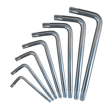
- Torx T20 screwdriver
- Torx T15 screwdriver
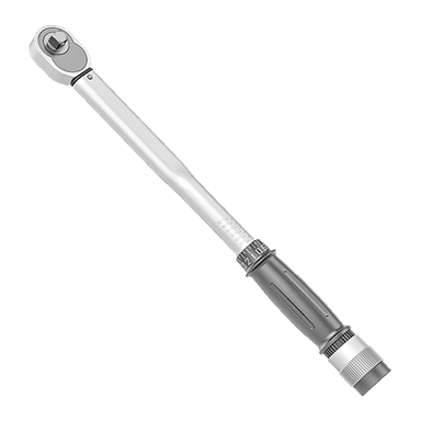
- 1/4-inch drive inch-pound torque wrench
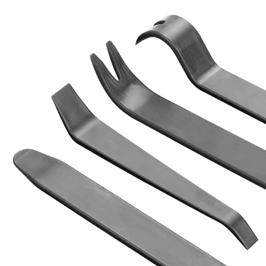
- Small plastic trim tool
- Clean microfiber cloth
- Nitrile work gloves
- Safety glasses
- OBD-II code scanner
🔩 Required Parts
HowToo sells all the parts you need for this repair:
- Vehicle-matched mass air flow sensor - Qty: 1
Use an 8-pin sensor only if your original connector has eight terminal positions. Use the 4-pin sensor only if the original has four. Connector count wins here, every time.
📋 Before You Begin
- Park your Silverado on level ground and shift into Park.
- Set the parking brake and switch the ignition completely off.
- Open the hood and locate the air-filter box on the passenger side.
- Follow the large intake tube from the air box toward the engine. The MAF sensor is mounted in that airflow path.
- Compare the new and old sensors. Check the connector shape, terminal count, screw pattern, and airflow orientation.
- Take a phone photo of the original sensor’s position before removing it.
🔨 Step-by-Step Instructions
Follow these steps in order:
Step 1: Disconnect the Electrical Connector
- Put on the nitrile work gloves and safety glasses.
- Press or gently lift the connector’s locking tab with the small plastic trim tool.
- Pull the connector straight from the sensor body. Pull on the plug, not the wires.
- If the connector has a colored secondary lock, slide that lock back before pressing the main release.
Step 2: Remove the Original Sensor
- Inspect the screw heads and select either the Torx T15 screwdriver or Torx T20 screwdriver.
- Remove the sensor retaining screw or screws while supporting the sensor with your free hand.
- Place the screws on the clean microfiber cloth so they can’t fall into the intake.
- Lift the sensor straight out. Don’t twist or pry against the delicate sensing element.
- Slow hands save tiny screws.
Step 3: Inspect the Intake Opening
- Use the clean microfiber cloth to wipe only the outside edge of the mounting opening.
- Check the old sensor’s seal. Make sure it came out with the sensor and isn’t stuck in the intake housing.
- Inspect the connector for bent terminals, moisture, oil, or green corrosion.
- Don’t push the cloth, fingers, or tools into the intake passage.
Step 4: Install the New Sensor
- Hold the new sensor by its plastic body. Don’t touch the sensing element.
- Match its orientation to your reference photo and any airflow arrow on the original sensor or housing.
- Insert the sensor squarely so its seal seats evenly without force.
- Start each retaining screw by hand, then tighten evenly with the correct Torx T15 screwdriver or Torx T20 screwdriver.
- If the replacement sensor supplies a torque specification, use the 1/4-inch drive inch-pound torque wrench and follow that value. Otherwise, tighten only until the sensor is seated and the screws are lightly snug.
- Don’t overtighten these small screws. The plastic intake housing can strip or crack.
Step 5: Reconnect the Harness
- Push the electrical connector onto the new sensor until the locking tab clicks.
- Re-engage the colored secondary lock if equipped.
- Pull lightly on the connector body to confirm it’s locked.
- Check that the wiring isn’t stretched, pinched, or rubbing against a sharp edge.
Step 6: Clear Stored Fault Codes
- Connect the OBD-II code scanner to the diagnostic port below the driver-side instrument panel.
- Switch the ignition on without starting the engine.
- Use the scanner’s erase-code function to clear the MAF-related diagnostic codes.
- Switch the ignition off for approximately 30 seconds, then disconnect the scanner.
✅ After Repair
- Start the engine and let it idle for three to five minutes.
- The idle may adjust briefly while the engine computer relearns airflow readings.
- Confirm the check-engine light stays off and the engine idles smoothly.
- Inspect the intake tube and air-box cover for loose clamps, cracks, or gaps that could admit unmetered air.
- Take a short, gentle test drive and rescan with the OBD-II code scanner.
- If a MAF code returns, inspect the connector, wiring, air-filter installation, and intake duct before replacing anything else.
💰 DIY vs Shop Cost
Shop Cost: $170-$350 parts and labor
DIY Cost: $71-$85 for the currently listed sensor options
You Save: Approximately $85-$275 by doing it yourself!
Shop labor rates vary but typically run $100-$150/hour. This repair takes a shop approximately 0.3-0.6 hour.
🎯 Ready to get started?
HowToo makes it easy: same-day/2-day shipping on every part, plus all the tools and specialty tools you need! Check out the parts and tools sections below to add everything to your cart.