



How to Replace Front Window Regulators on a 2014-2019 Toyota Highlander
Step-by-step DIY guide with tools, parts, torque specs, safety tips, and testing for 2014, 2015, 2016, 2017, 2018, 2019
How to Replace Front Window Regulators on a 2014-2019 Toyota Highlander
Step-by-step DIY guide with tools, parts, torque specs, safety tips, and testing for 2014, 2015, 2016, 2017, 2018, 2019


🔧 A/C Compressor - Replacement
This repair replaces the failed A/C compressor on your Highlander. The compressor is the pump that moves refrigerant through the air conditioning system, so the refrigerant must be professionally recovered before any lines are opened.
Difficulty Level: Advanced | Estimated Time: 3-5 hours plus A/C evacuation and recharge
⚠️ Safety & Precautions
- ⚠️ Do not vent refrigerant into the air. The A/C system must be recovered with professional refrigerant recovery equipment before removing the compressor.
- ⚠️ Refrigerant can cause frostbite and eye injury. Wear safety glasses and nitrile gloves any time A/C fittings are handled.
- ⚠️ Disconnect the negative battery cable before working near the compressor clutch connector and drive belt area.
- ⚠️ Support your Highlander securely with jack stands. Never work under a vehicle supported only by a jack.
- ⚠️ Replace the receiver/drier or desiccant element whenever the compressor is replaced to protect the new compressor from moisture and debris.
- ⚠️ If the old compressor failed internally and spread metal debris, the condenser may need replacement and the lines/evaporator should be flushed by an A/C-capable shop.
🔧 Required Tools
You'll need the following tools for this repair:
- 10mm socket
- 12mm socket
- 14mm socket
- 19mm socket
- 3/8-inch ratchet
- 1/2-inch ratchet
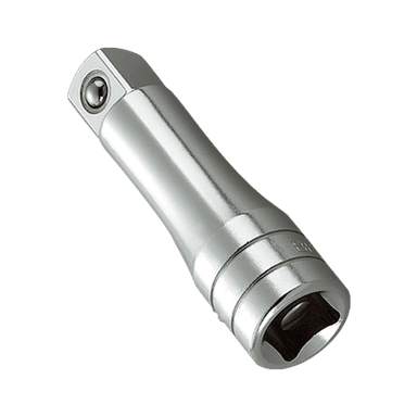
- 3/8-inch extension set
- Serpentine belt tool 14mm
- Torque wrench 5-80 ft-lbs
- Trim clip removal tool
- Flat-blade screwdriver 1/4-inch
- Pick tool set
- A/C manifold gauge set R-134a (specialty)
- A/C vacuum pump 3 CFM minimum (specialty)
- Refrigerant recovery machine R-134a (specialty)
- Digital scale 0-50 lb (specialty)
- UV leak detection light (specialty)
- Floor jack rated 3-ton minimum
- Jack stands rated 3-ton minimum
- Wheel chocks
- Safety glasses
- Nitrile gloves
🔩 Required Parts
HowToo sells all the parts you need for this repair:
- A/C compressor with clutch - Qty: 1
- A/C compressor O-ring seal kit - Qty: 1
- Receiver/drier or desiccant element - Qty: 1
- Serpentine drive belt - Qty: 1
- PAG 46 refrigerant oil - Qty: As required after oil balancing
- R-134a refrigerant - Qty: Charge by under-hood label specification
- A/C flush solvent - Qty: 1, if compressor failed internally
📋 Before You Begin
- 🅿️ Park your Highlander on level ground, shift to Park, set the parking brake, and chock the rear wheels.
- ❄️ Have the A/C refrigerant professionally recovered before opening the system. Recovery means removing and storing the refrigerant with a dedicated machine.
- 🔋 Use a 10mm socket to disconnect the negative battery cable. Move the cable so it cannot spring back onto the battery post.
- 🚗 Use a floor jack rated 3-ton minimum at the front jacking point, then place jack stands rated 3-ton minimum under the front support points.
- 🧰 Keep every A/C opening capped or taped after removal. Moisture in the air can damage the system.
- 📌 Assumption: This procedure is for your Highlander’s stock 2.7L FWD layout using R-134a refrigerant.
🔨 Step-by-Step Instructions
Follow these steps in order:
Step 1: Recover the refrigerant
- Use an A/C manifold gauge set R-134a and refrigerant recovery machine R-134a to recover the refrigerant from the high and low service ports.
- A manifold gauge set is a hose and gauge tool used to connect safely to the A/C system.
- If you do not own recovery equipment, have a shop recover the refrigerant first, then bring your Highlander home for the compressor replacement.
- Never loosen A/C lines under pressure.
Step 2: Disconnect the battery
- Use a 10mm socket and 3/8-inch ratchet to loosen the negative battery terminal nut.
- Remove the negative cable from the battery and isolate it away from the post.
Step 3: Raise and support the front
- Place wheel chocks behind the rear wheels.
- Use a floor jack rated 3-ton minimum to lift the front of your Highlander.
- Place jack stands rated 3-ton minimum under the approved front support points and gently lower the vehicle onto them.
- Shake the vehicle lightly by hand to confirm it is stable before going underneath.
Step 4: Remove the right front lower splash shield
- Use a trim clip removal tool to remove plastic push clips from the lower splash shield.
- Use a 10mm socket and 3/8-inch ratchet to remove any 10mm bolts holding the shield.
- Set the splash shield aside.
- A push clip is a reusable plastic fastener that expands when the center pin is pushed in.
Step 5: Remove the serpentine belt
- Before removing the belt, take a phone photo of the belt routing.
- Use a serpentine belt tool 14mm on the belt tensioner and rotate the tensioner to release belt tension.
- A belt tensioner is a spring-loaded pulley that keeps the belt tight.
- Slide the belt off the A/C compressor pulley, then remove it from the engine.
- Photo first, belt confusion avoided.
Step 6: Disconnect the compressor electrical connector
- Locate the A/C compressor at the lower front side of the engine.
- Use your fingers or a flat-blade screwdriver 1/4-inch to gently release the lock tab on the compressor clutch connector.
- Pull the connector straight off. Do not pull on the wires.
Step 7: Remove the A/C line fittings from the compressor
- Confirm again that the A/C system has been fully recovered.
- Use a 10mm socket or 12mm socket with a 3/8-inch ratchet to remove the suction and discharge line retaining bolts at the compressor.
- Carefully pull the refrigerant lines away from the compressor.
- Use a pick tool set to remove the old O-rings from the line ends.
- Immediately cap or tape the open A/C lines to keep dirt and moisture out.
Step 8: Remove the old compressor
- Support the compressor with one hand.
- Use a 12mm socket or 14mm socket, 3/8-inch extension set, and 3/8-inch ratchet to remove the compressor mounting bolts.
- Lower the compressor out through the bottom of the engine bay.
- Keep the compressor upright so oil does not spill unexpectedly.
Step 9: Balance compressor oil
- Drain oil from the old compressor into a clean measuring container by turning the compressor hub by hand.
- Drain the shipping oil from the new compressor into a clean measuring container.
- Add back the correct amount of PAG 46 refrigerant oil to the new compressor to match the amount removed, unless the compressor instructions say otherwise.
- Use your hand to rotate the new compressor hub 10 turns to distribute the oil.
- Oil balancing means matching the oil amount so the system is not overfilled or underfilled.
Step 10: Install the new compressor
- Position the new compressor in place from below.
- Start all mounting bolts by hand first to avoid cross-threading.
- Use a 12mm socket or 14mm socket, 3/8-inch extension set, and torque wrench 5-80 ft-lbs to tighten the compressor mounting bolts.
- Torque to 25 Nm (18 ft-lbs) unless the compressor manufacturer specifies a different value.
Step 11: Replace the A/C line O-rings
- Use a pick tool set to confirm the old O-rings are removed from both line fittings.
- Lightly coat the new O-rings with clean PAG 46 refrigerant oil.
- Install the new O-rings by hand. Do not use sharp tools to roll them on.
- An O-ring is a small rubber seal that prevents refrigerant leaks at the fitting.
Step 12: Reconnect the A/C lines
- Remove the caps or tape from the lines and compressor ports.
- Push each line straight into its compressor port by hand.
- Use a 10mm socket or 12mm socket and torque wrench 5-80 ft-lbs to tighten the line retaining bolts.
- Torque to 9 Nm (80 in-lbs).
- Straight fittings prevent O-ring damage.
Step 13: Replace the receiver/drier or desiccant element
- Use a 10mm socket, 12mm socket, 3/8-inch ratchet, and pick tool set to remove and replace the receiver/drier or desiccant element according to the replacement part design.
- Install new O-rings from the A/C compressor O-ring seal kit and lightly coat them with PAG 46 refrigerant oil.
- Tighten small A/C line fasteners with a torque wrench 5-80 ft-lbs.
- Torque to 9 Nm (80 in-lbs) for small A/C line retaining bolts unless the replacement part instructions specify otherwise.
Step 14: Reconnect the compressor connector
- Push the electrical connector onto the compressor until the lock clicks.
- Gently tug the connector by hand to confirm it is seated.
Step 15: Install the serpentine belt
- Route the belt over the pulleys using your photo from Step 5.
- Use the serpentine belt tool 14mm to rotate the tensioner.
- Slide the belt over the final pulley, then slowly release the tensioner.
- Check that the belt ribs are seated correctly in every grooved pulley.
Step 16: Reinstall the splash shield
- Position the lower splash shield back in place.
- Use a trim clip removal tool to reinstall the push clips.
- Use a 10mm socket and 3/8-inch ratchet to reinstall the shield bolts.
- Torque to 5 Nm (44 in-lbs) for small splash shield bolts.
Step 17: Lower the vehicle and reconnect the battery
- Use the floor jack rated 3-ton minimum to raise the front slightly off the jack stands.
- Remove the jack stands rated 3-ton minimum, then lower your Highlander carefully.
- Use a 10mm socket and 3/8-inch ratchet to reconnect the negative battery cable.
- Torque to 5 Nm (44 in-lbs) for the battery terminal clamp.
Step 18: Evacuate the A/C system
- Connect the A/C manifold gauge set R-134a to the high and low service ports.
- Connect the A/C vacuum pump 3 CFM minimum to the center hose of the manifold gauge set.
- Run the vacuum pump for at least 30-45 minutes to remove air and moisture.
- Close the manifold valves and confirm the system holds vacuum for 10-15 minutes.
- If vacuum drops, use a UV leak detection light after charging with dye-equipped refrigerant or leak dye to locate the leak.
Step 19: Recharge the A/C system
- Use a digital scale 0-50 lb to charge the exact refrigerant weight listed on your Highlander’s under-hood A/C label.
- Use only R-134a refrigerant.
- Start the engine, set A/C to MAX cold, blower high, and windows open.
- Continue charging through the low side until the specified weight has entered the system.
- Correct refrigerant weight matters most.
✅ After Repair
- ✅ With the engine running and A/C on, confirm the compressor clutch engages and cycles normally.
- ✅ Check for cold air at the center vents after several minutes of operation.
- ✅ Use an A/C manifold gauge set R-134a to verify pressures are stable and reasonable for the outside temperature.
- ✅ Inspect all compressor and drier fittings for oil residue or UV dye leaks.
- ✅ Listen for belt squeal, rattling, or grinding. Shut the engine off immediately if the belt is not tracking correctly.
- ✅ If the old compressor failed internally, have the system inspected for debris before long-term use.
💰 DIY vs Shop Cost
Shop Cost: $1,100-$1,900 (parts + labor + recovery/recharge)
DIY Cost: $450-$950 (parts only, not including recovery/recharge equipment)
You Save: $350-$900 by doing it yourself!
Shop labor rates vary but typically run $100-$150/hour. This repair takes a shop approximately 3-5 hours.
🎯 Ready to get started?
HowToo makes it easy: same-day/2-day shipping on every part, plus all the tools and specialty tools you need! Check out the parts and tools sections below to add everything to your cart.
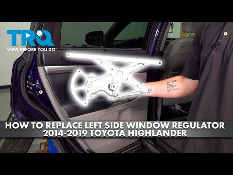
🔧 Front Window Regulators - Replacement
This repair replaces the front power window regulators in your Highlander. The regulator is the scissor/cable mechanism inside the door that moves the glass up and down; when it fails, the glass may drop, move slowly, bind, or stop working.
Difficulty Level: Intermediate | Estimated Time: 1.5-2.5 hours per door
⚠️ Safety & Precautions
- ⚠️ Disconnect the negative battery cable before unplugging door electrical connectors.
- ⚠️ Support the door glass before removing the regulator. Unsupported glass can drop and shatter.
- ⚠️ Wear safety glasses and cut-resistant gloves. Door glass and inner door metal edges can injure you.
- ⚠️ Do not turn the ignition on while door connectors are unplugged. This can set body control or airbag-related warning codes.
- ⚠️ Keep fingers away from the regulator tracks. The mechanism can pinch hard.
🔧 Required Tools
You'll need the following tools for this repair:
- 10mm socket
- Phillips #2 screwdriver
- 1/4-inch ratchet
- 3/8-inch ratchet
- 3-inch extension 1/4-inch drive
- Plastic trim removal tool set
- Panel clip removal pliers
- Flat-blade screwdriver 1/4-inch
- Pick tool set
- Painter’s tape 2-inch
- Suction cup glass holder 4-inch (specialty)
- Torque wrench 20-200 in-lbs
- Shop towel set
- Safety glasses
- Cut-resistant gloves
🔩 Required Parts
HowToo sells all the parts you need for this repair:
- Front driver window regulator with motor - Qty: 1
- Front passenger window regulator with motor - Qty: 1
- Front door trim panel clips - Qty: 1 pack
- Butyl door vapor barrier sealant - Qty: 1 roll, if original sealant is damaged
📋 Before You Begin
- 🅿️ Park your Highlander on level ground and set the parking brake.
- 🔑 Turn the ignition off and remove the key from the vehicle.
- 🪟 If the window still moves, lower or raise the glass until the glass mounting bolts are visible through the access holes in the inner door panel.
- 🔋 Use a 10mm socket to disconnect the negative battery cable, then wait at least 90 seconds before unplugging door connectors.
- 📌 This procedure applies to both front doors. The driver door has extra master switch wiring, but the repair process is nearly the same.
🔨 Step-by-Step Instructions
Follow these steps in order:
Step 1: Disconnect the battery
- Use a 10mm socket and 3/8-inch ratchet to loosen the negative battery terminal nut.
- Lift the negative cable off the battery post and place it where it cannot touch the battery.
- Wait at least 90 seconds before unplugging connectors in the door.
Step 2: Remove the front door switch panel
- Use a plastic trim removal tool set to gently pry up the window switch panel from the armrest.
- A trim tool is a plastic pry tool that removes panels without scratching them.
- Use a flat-blade screwdriver 1/4-inch only if needed to press connector lock tabs.
- Unplug the window switch connectors by pressing the locking tabs and pulling the connectors straight out.
- Plastic tools prevent door panel scratches.
Step 3: Remove visible door panel screws
- Use a pick tool set to carefully remove small screw covers in the door pull and inside handle area.
- Use a Phillips #2 screwdriver to remove the screws behind the covers.
- Use a 10mm socket, 3-inch extension 1/4-inch drive, and 1/4-inch ratchet if your replacement-door hardware uses 10mm bolts instead of Phillips screws.
- Place the screws on a shop towel set so they do not roll away.
Step 4: Release the door trim panel clips
- Slide a plastic trim removal tool set between the door panel and the metal door shell at the lower edge.
- Gently pry outward to pop the first clip loose.
- Use panel clip removal pliers to release stubborn clips without tearing the door panel.
- Work around the sides and bottom of the panel until all clips are free.
- Lift the door panel straight upward to unhook it from the window ledge.
Step 5: Disconnect handle cables and courtesy light wiring
- Hold the door panel close to the door.
- Use your fingers or a pick tool set to release the inside door handle cable retainers.
- Unhook the cable ends from the handle levers.
- Use a flat-blade screwdriver 1/4-inch to press any courtesy light connector lock tab, then unplug it.
- Set the door panel on a clean shop towel set.
Step 6: Peel back the vapor barrier
- Use a plastic trim removal tool set to gently separate the clear plastic vapor barrier from the black butyl sealant.
- A vapor barrier is the plastic sheet that keeps water inside the door from reaching the cabin trim.
- Peel it back only as far as needed to access the regulator and glass bolts.
- If the butyl stretches, use a pick tool set to guide it back onto the door.
- Do not tear the vapor barrier. Water leaks can happen later.
Step 7: Position the glass mounting bolts
- If the window still works, temporarily reconnect the battery with a 10mm socket, reconnect the switch, and move the glass until the glass clamp bolts line up with the access holes.
- Turn the ignition off, unplug the switch again, and disconnect the negative battery cable with the 10mm socket.
- If the window does not work, gently move the glass by hand while guiding the regulator through the access holes.
- Do not force the glass. If it binds, stop and inspect the track.
Step 8: Support the door glass
- Raise the glass fully by hand until it is closed in the upper window frame.
- Use painter’s tape 2-inch to tape the glass over the top of the door frame in several long strips.
- Install a suction cup glass holder 4-inch on the glass for extra control.
- A suction cup glass holder is a handle that sticks to the glass so you can hold it safely.
- Use extra tape. Glass is heavy.
Step 9: Loosen the glass clamp bolts
- Use a 10mm socket, 3-inch extension 1/4-inch drive, and 1/4-inch ratchet to loosen the two glass clamp bolts through the access holes.
- Do not fully remove the bolts unless the clamp design requires it.
- Lift the glass fully into the closed position and confirm the tape holds it securely.
Step 10: Unplug the window motor connector
- Locate the window motor connector on the regulator assembly.
- Use a flat-blade screwdriver 1/4-inch to press the connector lock tab if it is tight.
- Pull the connector straight out from the motor.
Step 11: Remove the old regulator assembly
- Use a 10mm socket, 3-inch extension 1/4-inch drive, and 1/4-inch ratchet to remove the regulator mounting bolts.
- Use the same 10mm socket to remove the motor mounting bolts if the motor mounts separately to the door.
- Support the regulator with one hand while removing the last bolt.
- Fold the regulator slightly and remove it through the large service opening in the door.
- Be patient. The assembly comes out at an angle.
Step 12: Compare the new and old regulators
- Place both regulators on a shop towel set.
- Confirm the bolt hole locations, motor connector shape, glass clamp position, and cable routing match.
- If the new regulator ships with shipping locks or clips, remove them only when the instructions say to.
Step 13: Install the new regulator assembly
- Insert the new regulator through the door service opening.
- Start every mounting bolt by hand first.
- Use a 10mm socket, 3-inch extension 1/4-inch drive, and torque wrench 20-200 in-lbs to tighten the regulator mounting bolts.
- Torque to 8 Nm (71 in-lbs).
- Reconnect the window motor connector until it clicks.
Step 14: Attach the glass to the regulator
- Carefully remove only enough painter’s tape 2-inch to lower the glass by hand into the regulator clamps.
- Use the suction cup glass holder 4-inch to guide the glass straight down.
- Make sure the glass sits evenly in both clamps.
- Use a 10mm socket, 3-inch extension 1/4-inch drive, and torque wrench 20-200 in-lbs to tighten the glass clamp bolts.
- Torque to 8 Nm (71 in-lbs).
Step 15: Test the regulator before closing the door
- Reconnect the negative battery cable temporarily with a 10mm socket.
- Reconnect the window switch panel connector by hand.
- Turn the ignition to ON and run the window down and up once.
- Watch the glass through the door opening. It should move smoothly without tilting or scraping.
- If it binds, turn ignition off and loosen the glass clamp bolts with the 10mm socket, realign the glass, then retighten to 8 Nm (71 in-lbs).
Step 16: Initialize the power window auto function
- With the door switch connected and ignition ON, fully close the window using the switch.
- Hold the switch in the UP position for 2-5 seconds after the glass reaches the top.
- Lower the window fully, then hold the switch in the DOWN position for 2-5 seconds.
- Raise the window again and check one-touch up/down operation if equipped.
- Initialization teaches the window motor where fully open and fully closed are.
Step 17: Reinstall the vapor barrier
- Turn ignition off and disconnect the negative battery cable again with a 10mm socket.
- Press the vapor barrier back into the original butyl sealant by hand.
- If the sealant no longer sticks, apply butyl door vapor barrier sealant around the loose areas.
- Make sure wiring passes through the correct openings and is not pinched.
Step 18: Reinstall the door trim panel
- Reconnect the courtesy light connector by hand.
- Reconnect the inside handle cables by hand and snap the retainers into place.
- Hang the top of the door panel over the window ledge.
- Line up the clips, then press around the panel by hand until each clip snaps in.
- Use front door trim panel clips to replace any broken clips.
Step 19: Reinstall screws and switch panel
- Use a Phillips #2 screwdriver to reinstall the door panel screws.
- If equipped with 10mm bolts, use a 10mm socket, 3-inch extension 1/4-inch drive, and torque wrench 20-200 in-lbs.
- Torque to 3 Nm (27 in-lbs) for small trim screws or bolts.
- Reconnect the window switch connectors by hand.
- Snap the switch panel into the armrest by pressing straight down.
Step 20: Repeat on the other front door
- Repeat Steps 2-19 for the opposite front door.
- The passenger side has fewer switch connectors, but the glass and regulator steps are the same.
Step 21: Reconnect the battery for final testing
- Use a 10mm socket and 3/8-inch ratchet to reconnect the negative battery cable.
- Torque to 5 Nm (44 in-lbs).
- Test both front windows from their own switches and from the driver master switch.
✅ After Repair
- ✅ Confirm both front windows move smoothly from fully closed to fully open.
- ✅ Confirm the driver master switch operates both front windows.
- ✅ Check that auto up/down works if equipped. Repeat the initialization step if needed.
- ✅ Open and close each front door while operating the window to check for rattles or binding.
- ✅ Pour a small amount of water over the outside window area and check inside for vapor barrier leaks.
💰 DIY vs Shop Cost
Shop Cost: $650-$1,100 for both front regulators (parts + labor)
DIY Cost: $180-$450 for both front regulators and clips (parts only)
You Save: $300-$650 by doing it yourself!
Shop labor rates vary but typically run $100-$150/hour. This repair takes a shop approximately 2-4 hours for both front doors.
🎯 Ready to get started?
HowToo makes it easy: same-day/2-day shipping on every part, plus all the tools and specialty tools you need! Check out the parts and tools sections below to add everything to your cart.