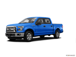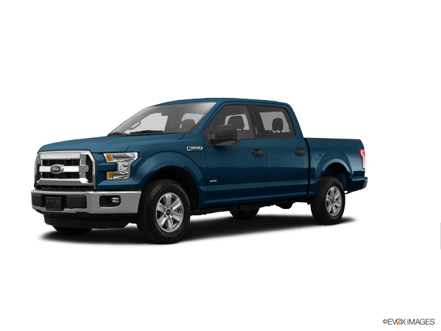

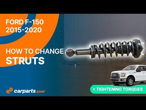

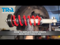



How to Replace Front Struts on a 2015 Ford F-150 – DIY Repair Guide
Step-by-step F-150 front strut replacement with tools, parts list, torque specs, and safety tips for 2015, 2016, 2017, 2018, 2019, 2020
How to Replace Front Struts on a 2015 Ford F-150 – DIY Repair Guide
Step-by-step F-150 front strut replacement with tools, parts list, torque specs, and safety tips for 2015, 2016, 2017, 2018, 2019, 2020


🔧 F-150 - Front Strut Assembly Replacement
Your F-150 uses front coil-over shock assemblies, commonly called struts. The safest beginner method is installing complete preassembled units, which avoids compressing the powerful coil springs.
Assumption: These instructions cover the stock front suspension, with separate 2WD and 4WD precautions where necessary.
Difficulty Level: Advanced | Estimated Time: 5-7 hours
⚠️ Safety & Precautions
- ⚠️ Never loosen the large center nut on top of the assembly. That nut retains the compressed coil spring.
- ⚠️ Use complete preassembled struts unless a trained technician with a wall-mounted spring compressor transfers the springs.
- ⚠️ Support your F-150 with correctly positioned jack stands. Never work under a vehicle supported only by a floor jack.
- ⚠️ Keep the brake hose, ABS sensor wire, and—on 4WD models—the front CV axle from being stretched.
- ⚠️ Replace one side at a time so the assembled side remains a reference.
- ⚠️ Several suspension fasteners are extremely tight. Stop if your torque wrench cannot reach the specified value.
- ⚠️ The battery does not need to be disconnected.
🔧 Required Tools
You'll need the following tools for this repair:
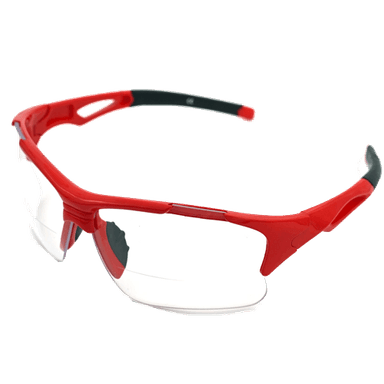
- Safety glasses
- Mechanic's gloves
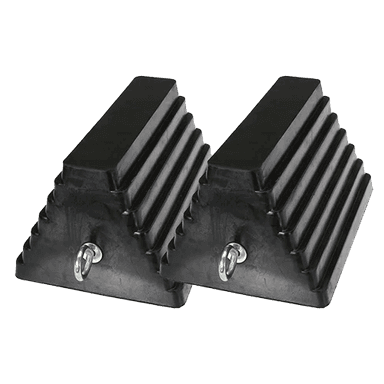
- Wheel chocks
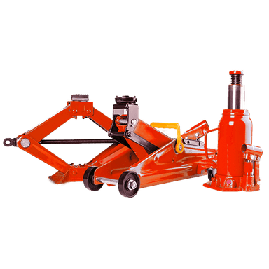
- Floor jack (rated 3-ton minimum)
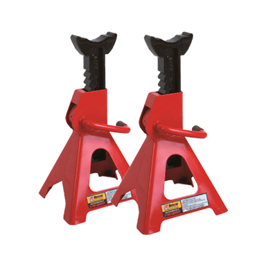
- Jack stands (rated 3-ton minimum)
- Second hydraulic jack (rated 2-ton minimum)
- 1/2-inch-drive breaker bar (24-inch minimum)
- 1/2-inch-drive torque wrench (30-150 ft-lbs)
- 3/4-inch-drive torque wrench (50-300 ft-lbs)
- 3/4-inch-drive breaker bar (36-inch minimum)
- 13mm deep socket
- 15mm socket
- 18mm socket
- 21mm deep socket
- 24mm socket
- 27mm socket
- 30mm socket
- 13mm combination wrench
- 15mm combination wrench
- 18mm combination wrench
- 21mm combination wrench
- 24mm combination wrench
- 27mm combination wrench
- 6mm hex-bit socket
- 1/2-inch-drive extension set
- 3/4-inch-drive extension set
- 18-inch pry bar
- Brass drift punch
- 32-ounce ball-peen hammer
- Paint marker
- Penetrating oil
- Wire brush
🔩 Required Parts
HowToo sells all the parts you need for this repair:
- Complete front strut assemblies - Replace in pairs - Qty: 2
- Front strut upper mounting nuts - Qty: 6
- Front strut lower bolt and nut sets - Qty: 2
- Lower control-arm pivot bolt and nut sets - Qty: 4
- Front stabilizer-bar link nuts - Qty: 2
- Front alignment service - Qty: 1
📋 Before You Begin
- 🚙 Park on solid, level ground. Select Park, engage the parking brake, and chock both rear wheels.
- 📏 Measure from the center of each front wheel to the lower edge of its fender and record the measurements.
- 🔩 Use a 21mm deep socket and breaker bar to loosen each front lug nut one-half turn.
- 🛞 Place the floor jack beneath the front crossmember, raise your F-150, and position jack stands under both frame rails.
- 🧰 Keep the second hydraulic jack available to support the lower control arm.
- 📱 No infotainment service mode, scan-tool command, battery registration, EPB procedure, or ADAS calibration mode is required.
🔨 Step-by-Step Instructions
Follow these steps in order:
Step 1: Remove the First Front Wheel
- Use the floor jack and jack stands to verify that the frame is securely supported.
- Use a 21mm deep socket to remove the lug nuts and wheel.
- Place the removed wheel flat beneath the frame as an additional precaution.
Step 2: Support the Lower Control Arm
- Position the second hydraulic jack under the broad, reinforced area of the lower control arm.
- Raise the jack only until it lightly supports the arm. Do not lift your F-150 away from the jack stand.
- A control arm is the hinged suspension member connecting the wheel assembly to the frame.
Step 3: Disconnect the Stabilizer-Bar Link
- Use a wire brush and penetrating oil on the stabilizer-bar link nut.
- Use an 18mm socket and 18mm wrench to remove the link nut. If the stud spins, hold its center with a 6mm hex-bit socket while turning the nut with an 18mm wrench.
- Swing the link clear without damaging its rubber boots.
Step 4: Free Nearby Hoses and Wiring
- Inspect the brake hose and ABS wheel-speed sensor wire around the strut and steering knuckle.
- Use a 10mm or 13mm socket, as fitted, to remove any bracket that prevents free suspension movement.
- Do not open the hydraulic brake hose. No brake bleeding is required.
Step 5: Loosen the Upper Mounting Nuts
- Open the hood and locate the three small nuts surrounding the top of the strut tower.
- Use a 15mm deep socket to loosen all three nuts, but leave each nut engaged by several full threads.
- Do not touch the large center nut. That center nut retains spring tension.
Step 6: Remove the Lower Strut Bolt
- Use a paint marker to mark the bolt orientation.
- Use the correctly fitting 27mm or 30mm socket and matching wrench to remove the lower strut nut. Ford used different fastener head sizes during production, so use only the socket that fits tightly.
- Use the second hydraulic jack to adjust control-arm height until the bolt is free of tension.
- Use a brass drift punch and 32-ounce hammer to drive out the lower bolt without damaging its threads.
Step 7: Create Removal Clearance
- Use a paint marker to outline both lower control-arm alignment washers against the frame brackets.
- Use a 24mm or 27mm socket, matching wrench, and breaker bar to remove the front and rear lower control-arm pivot nuts and bolts.
- Slowly lower the second hydraulic jack until the control arm swings down far enough to release the bottom of the strut.
- On a 4WD model, watch the CV axle—the jointed shaft driving the front wheel—and stop before either joint binds or separates.
- Do not let the steering knuckle hang from the brake hose or ABS wire.
Step 8: Remove the Strut Assembly
- Support the strut with one hand while using a 15mm deep socket to remove the three remaining upper nuts.
- Lower and angle the complete assembly through the wheel opening.
- Use an 18-inch pry bar only against strong control-arm surfaces if a small amount of extra clearance is needed.
- Do not pry against the CV boot, brake hose, steering rack boot, or aluminum steering knuckle.
Step 9: Compare the Replacement Assembly
- Place the old and new assemblies side by side.
- Confirm that the overall length, lower mounting sleeve, upper-stud pattern, spring seating, and left/right orientation match.
- Do not remove or loosen the new assembly's center shaft nut.
Step 10: Position the New Strut
- Guide the new assembly into the strut tower by hand.
- Install three new upper nuts by hand, leaving them slightly loose so the lower mount can move into alignment.
- Use the second hydraulic jack to raise the lower control arm toward the strut.
- Align the lower sleeve and install the new lower bolt in its original direction. Thread the new nut by hand.
Step 11: Reinstall the Lower Control Arm
- Use the second hydraulic jack and an 18-inch pry bar to align the control-arm bushings with their frame brackets.
- Install the new pivot bolts, washers, and nuts by hand.
- Use the paint-marker outlines to return the alignment washers close to their original positions.
- Snug the pivot nuts with a 24mm or 27mm socket, but do not apply final torque while the suspension hangs.
Step 12: Tighten the Strut and Link Fasteners
- Use a 15mm deep socket and torque wrench on the three upper mounting nuts. Torque to 70 Nm (52 ft-lbs).
- Use the correctly fitting socket, matching wrench, and 3/4-inch-drive torque wrench on the lower strut fastener. Torque to 406 Nm (300 ft-lbs).
- Use an 18mm socket and torque wrench on the stabilizer-bar link nut. Torque to 115 Nm (85 ft-lbs).
- Use a 10mm or 13mm socket to reinstall any removed hose or ABS-wire bracket firmly without pinching its wiring.
Step 13: Load and Tighten the Control-Arm Bushings
- Use the second hydraulic jack to raise the lower control arm until the wheel-center-to-fender measurement matches the number recorded before disassembly.
- Verify that your F-150 remains firmly seated on both frame jack stands.
- Use a 24mm or 27mm socket, matching wrench, and 3/4-inch-drive torque wrench on both lower control-arm pivot fasteners. Torque to 350 Nm (258 ft-lbs).
- Tightening rubber suspension bushings at normal ride height prevents premature bushing failure.
Step 14: Repeat on the Opposite Side
- Use the same listed tools and repeat Steps 1-13 on the opposite front corner.
- Continue supporting the control arm and protecting the brake hose, ABS wire, and 4WD CV axle.
Step 15: Install the Wheels
- Use a wire brush to clean rust or debris from the wheel-to-hub mounting surfaces.
- Install each wheel and start all lug nuts by hand.
- Use a 21mm deep socket to snug the nuts in a star pattern.
- Use the floor jack to raise your F-150, remove the jack stands, and lower it completely.
- Use a 21mm deep socket and torque wrench to tighten the lug nuts in a star pattern. Torque to 204 Nm (150 ft-lbs).
✅ After Repair
- ✅ Confirm that every brake-hose bracket and ABS-wire retainer is attached and clear of the tire.
- ✅ Turn the steering wheel fully left and right while stationary. Stop if anything stretches, rubs, or clicks.
- ✅ Drive slowly over a smooth route and listen for knocking, spring movement, or rubbing.
- ✅ Arrange a four-wheel alignment immediately because the lower control-arm alignment points were disturbed.
- ✅ Recheck wheel-lug torque after approximately 80-160 km.
- ✅ No scan-tool reset, battery registration, or infotainment reset is required.
💰 DIY vs Shop Cost
Shop Cost: ₹65,000-₹1,20,000 (parts + labor)
DIY Cost: ₹35,000-₹75,000 (parts only)
You Save: ₹30,000-₹45,000 by doing it yourself!
Panipat labor and imported-part pricing vary. This repair takes a shop approximately 4-6 hours, plus alignment.
🎯 Ready to get started?
HowToo makes it easy: same-day/2-day shipping on every part, plus all the tools and specialty tools you need! Check out the parts and tools sections below to add everything to your cart.