

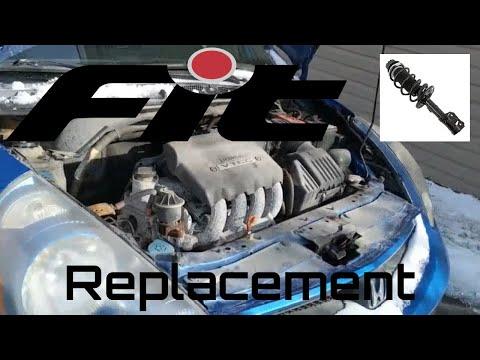


How to Replace Front Strut Assemblies on a 2007-2020 Honda Fit (Trim: LX)
Step-by-step instructions with required tools, parts, torque specs, and safety tips for 2007, 2008, 2009, 2010, 2011, 2012, 2013
How to Replace Front Strut Assemblies on a 2007-2020 Honda Fit (Trim: LX)
Step-by-step instructions with required tools, parts, torque specs, and safety tips for 2007, 2008, 2009, 2010, 2011, 2012, 2013


🔧 Fit - Front Strut Assembly Replacement
This procedure replaces both front struts on your Fit using complete, preassembled strut units. Complete assemblies are safest for a beginner because the coil spring is already installed and compressed.
Assumption: “Struts” means both front complete strut assemblies.
Difficulty Level: Intermediate | Estimated Time: 3-5 hours
⚠️ Safety & Precautions
- ⚠️ Replace front struts in pairs so handling and braking remain balanced.
- ⚠️ Never work beneath a vehicle supported only by a floor jack; use properly positioned jack stands.
- ⚠️ Do not loosen the large center shaft nut on the strut mount. The compressed coil spring can release with lethal force.
- ⚠️ Use complete preassembled struts. Servicing a bare strut requires a professional wall-mounted spring compressor.
- ⚠️ Support the steering knuckle after disconnecting the strut so the brake hose and CV axle are not damaged.
- ⚠️ Keep grease and oil away from the brake rotor and pads.
- Battery disconnection is not required.
🔧 Required Tools
You'll need the following tools for this repair:
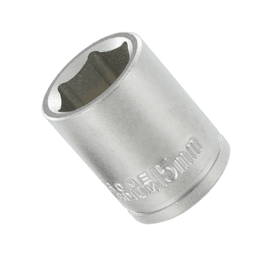
- 10mm socket
- 12mm socket
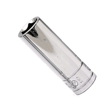
- 14mm deep socket
- 17mm socket
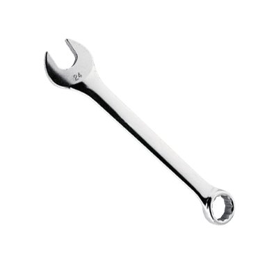
- 17mm combination wrench
- 19mm deep socket
- 6mm hex-bit socket
- 3/8-inch-drive ratchet
- 1/2-inch-drive breaker bar
- 1/2-inch-drive torque wrench rated 20-150 Nm
- Flat-blade trim tool
- Medium pry bar
- Ball-peen hammer (16-ounce)
- Paint marker
- Penetrating oil
- Mechanic’s wire rated 45 kg minimum
- Floor jack rated 2-ton minimum
- Jack stands rated 2-ton minimum
- Wheel chocks
- Safety glasses
- Mechanic’s gloves
🔩 Required Parts
HowToo sells all the parts you need for this repair:
- Front complete strut assemblies - Replace in pairs - Qty: 2
- Front strut-to-steering-knuckle self-locking nuts - Qty: 4
- Front stabilizer-link self-locking nuts - Qty: 2
- Front upper strut-mount nuts - Qty: 6
📋 Before You Begin
- Park your Fit on firm, level ground. Select Park or first gear, apply the parking brake, and switch the ignition off.
- Place wheel chocks securely behind both rear wheels.
- Open the hood before lifting the vehicle.
- Verify that the replacement assemblies are marked left and right. Brackets must face the same directions as the original units.
- Arrange a four-wheel alignment immediately after replacement. Strut removal changes front camber and toe.
🔨 Step-by-Step Instructions
Follow these steps in order:
Step 1: Loosen the Front Wheel Nuts
- Use a 19mm deep socket and 1/2-inch breaker bar to loosen each front wheel nut about one-half turn.
- Do not remove the wheel nuts while your Fit is still on the ground.
Step 2: Raise and Support the Vehicle
- Use the 2-ton floor jack at the front center jacking point beneath the engine-area subframe.
- Position 2-ton jack stands beneath the reinforced left and right front side support points.
- Lower your Fit onto the stands and gently push the body to verify stability.
- Use the 19mm deep socket and ratchet to remove the wheel nuts and both front wheels.
Step 3: Mark the Strut and Knuckle Position
- Use a paint marker to trace around the strut where it meets the steering knuckle. The steering knuckle is the metal wheel-support component behind the brake rotor.
- Mark the upper and lower bolt positions as a reference for reassembly.
- These marks help preserve the original alignment.
Step 4: Disconnect the Brake Hose and ABS Wire
- Use a 12mm socket and ratchet to remove the brake-hose bracket bolt from the strut.
- Use a flat-blade trim tool to carefully release the ABS wheel-speed sensor wire clip from its strut bracket.
- Do not open the brake hydraulic line or pull on the ABS wire.
- During installation, tighten the brake-hose bracket bolt to 22 Nm (16 ft-lbs).
Step 5: Disconnect the Stabilizer Link
- Spray the stabilizer-link nut threads lightly with penetrating oil.
- Use a 17mm combination wrench to turn the link nut. If the stud spins, hold its center with a 6mm hex-bit socket.
- Move the link stud out of the strut bracket without bending it.
- During installation, fit a new self-locking nut and tighten it to 38 Nm (28 ft-lbs).
Step 6: Support the Steering Knuckle
- Place the 2-ton floor jack beneath the steering knuckle and raise it only enough to support its weight.
- Use mechanic’s wire to loosely support the knuckle from a solid body or subframe point.
- Do not lift against the brake rotor, dust shield, or CV axle.
Step 7: Remove the Strut-to-Knuckle Fasteners
- Use a 19mm deep socket and breaker bar on the two strut-to-knuckle nuts while holding each bolt head with a 19mm socket and ratchet.
- Remove both nuts. Use a 16-ounce ball-peen hammer to tap the bolt ends until the bolts slide out.
- Use a medium pry bar only between the strut bracket and knuckle if gentle separation is needed.
- Keep the knuckle supported so it cannot pull outward and separate the inner CV joint.
- During installation, use new self-locking nuts and tighten both fasteners to 116 Nm (86 ft-lbs).
Step 8: Remove the Upper Mount Nuts
- Support the strut assembly with one hand from inside the wheel opening.
- Under the hood, use a 14mm deep socket and ratchet to remove the three small upper strut-mount nuts.
- Do not loosen the large center shaft nut.
- Lower the complete strut assembly carefully through the wheel opening.
- During installation, tighten the three upper mount nuts evenly to 44 Nm (33 ft-lbs).
Step 9: Compare and Install the New Assembly
- Place the old and new assemblies beside each other. Confirm equal overall layout and matching brake-hose, ABS-wire, and stabilizer-link brackets.
- Guide the new assembly into the strut tower without scraping the painted body.
- Install the three new upper mount nuts by hand. Use the 14mm deep socket only after every nut threads smoothly.
- Leave the upper nuts slightly loose until the lower strut bolts are installed.
Step 10: Attach the Strut to the Knuckle
- Use the 2-ton floor jack to adjust knuckle height until its holes align with the strut bracket.
- Insert both original bolts in their original directions and install new self-locking nuts.
- Align the paint marks. Use two 19mm sockets with the torque wrench and ratchet to tighten both fasteners to 116 Nm (86 ft-lbs).
- Use the 14mm deep socket and torque wrench to tighten the three upper mount nuts evenly to 44 Nm (33 ft-lbs).
Step 11: Reconnect the Link, Hose, and ABS Wire
- Insert the stabilizer-link stud into its bracket. Use the 17mm socket, 17mm wrench, and 6mm hex-bit socket as needed, then tighten the new nut to 38 Nm (28 ft-lbs).
- Position the brake hose without twisting it. Use the 12mm socket and torque wrench to tighten its bracket bolt to 22 Nm (16 ft-lbs).
- Use your gloved fingers to press the ABS-wire clip fully into its bracket.
- Remove the mechanic’s wire and lower the floor jack from beneath the knuckle.
Step 12: Repeat on the Opposite Side
- Repeat Steps 3 through 11 for the other front strut using the same listed tools and torque values.
- Install the correct left- or right-side assembly. Do not interchange sides.
Step 13: Reinstall the Wheels
- Clean the wheel-to-hub contact surfaces with a gloved hand and dry cloth.
- Install each wheel and start all wheel nuts by hand.
- Use the 19mm deep socket and ratchet to snug the nuts in a crisscross pattern.
- Raise your Fit with the 2-ton floor jack, remove the jack stands, and lower it until the tires contact the ground.
- Use the 19mm deep socket and torque wrench to tighten the wheel nuts in a crisscross pattern to 108 Nm (80 ft-lbs).
✅ After Repair
- Turn the steering wheel fully left and right while stationary. Listen for binding, spring popping, or contact with a brake hose or ABS wire.
- Drive slowly in a safe area. Confirm normal steering response and verify that no warning lights appear.
- Stop immediately if the steering wheel is severely off-center, the vehicle pulls strongly, or knocking develops.
- Have a four-wheel alignment performed before normal driving to prevent poor handling and rapid tire wear.
- Ask the alignment shop to inspect front camber and toe and confirm that the steering wheel is centered.
- Recheck wheel-nut torque at 108 Nm (80 ft-lbs) after approximately 80-160 km.
💰 DIY vs Shop Cost
Shop Cost: ₹32,000-₹58,000 (parts + labor + alignment)
DIY Cost: ₹18,000-₹38,000 (parts + alignment)
You Save: ₹10,000-₹20,000 by doing it yourself!
Labor rates around Sonīpat vary by workshop. This repair takes a shop approximately 2.5-4 hours, plus alignment time.
🎯 Ready to get started?
HowToo makes it easy: same-day/2-day shipping on every part, plus all the tools and specialty tools you need! Check out the parts and tools sections below to add everything to your cart.