


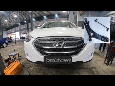


How to Replace Front Lower Control Arms on a 2015 Hyundai Tucson
Step-by-step suspension repair guide with tools, parts, torque specs, and safety tips for 2010, 2011, 2012, 2013, 2014, 2015
How to Replace Front Lower Control Arms on a 2015 Hyundai Tucson
Step-by-step suspension repair guide with tools, parts, torque specs, and safety tips for 2010, 2011, 2012, 2013, 2014, 2015
🔧 Tucson - Front Lower Control Arm Replacement
This repair replaces the front lower control arms, which connect the front wheels to the subframe and hold the wheel in the correct position. Worn control arm bushings or ball joints can cause clunks, loose steering, uneven tire wear, or pulling.
Difficulty Level: Intermediate | Estimated Time: 2.5-4 hours
⚠️ Safety & Precautions
- ⚠️ Support your Tucson with jack stands before working underneath it. Never rely on a jack alone.
- ⚠️ Work on level ground with the parking brake set and the rear wheels chocked.
- ⚠️ Front suspension parts may be under tension. Keep hands clear while separating the ball joint.
- ⚠️ Do not hammer directly on the axle, steering knuckle, or ball joint threads.
- ⚠️ Control arm bolts should be final-tightened at normal ride height to prevent bushing damage.
- ⚠️ A professional wheel alignment is required after this repair.
🔧 Required Tools
You'll need the following tools for this repair:
- Floor jack (rated 3-ton minimum)
- Jack stands (rated 3-ton minimum)
- Wheel chocks
- Safety glasses
- Mechanic gloves
- Breaker bar 1/2-inch drive
- Torque wrench 1/2-inch drive
- Impact wrench 1/2-inch drive
- Socket ratchet 1/2-inch drive
- 17mm socket
- 19mm socket
- 21mm socket
- 22mm socket
- 17mm wrench
- 19mm wrench
- 21mm wrench
- 22mm wrench
- Ball joint separator (specialty)
- Pry bar 18-inch
- Hammer 3-lb dead blow
- Needle-nose pliers
- Paint marker
- Penetrating oil
- Wire brush
🔩 Required Parts
HowToo sells all the parts you need for this repair:
- Front lower control arm assembly - Qty: 1 per side
- Front lower control arm assemblies - Replace in pairs - Qty: 2
- Lower ball joint cotter pin - Qty: 1 per side
- Lower control arm mounting bolts and nuts - Qty: as needed
- Stabilizer bar link nut - Qty: 1 per side if removed
📋 Before You Begin
- 🚗 Park your Tucson on flat, solid ground.
- 🔒 Set the parking brake and place wheel chocks behind the rear wheels.
- 🧰 Spray penetrating oil on the control arm bolts, ball joint nut, and stabilizer link fasteners before starting.
- 📌 A ball joint separator is a tool that presses the ball joint stud out of the steering knuckle without damaging the parts around it.
- 📌 A torque wrench is a tool that tightens bolts to an exact tightness so they are not too loose or too tight.
- 📌 Final tightening of the control arm bushing bolts must be done with the suspension loaded at normal ride height.
🔨 Step-by-Step Instructions
Follow these steps in order:
Step 1: Loosen the Front Wheel Lug Nuts
- Use a 21mm socket and breaker bar 1/2-inch drive to loosen the front wheel lug nuts about 1/2 turn.
- Do not remove the lug nuts yet.
- Loosen wheels before lifting.
Step 2: Raise and Support the Front of the Vehicle
- Use a floor jack (rated 3-ton minimum) to lift the front of your Tucson at the front subframe lift point.
- Place jack stands (rated 3-ton minimum) under the proper front support points.
- Gently lower the vehicle onto the jack stands.
- Keep the floor jack lightly touching the subframe as a backup support.
Step 3: Remove the Front Wheel
- Use a 21mm socket and socket ratchet 1/2-inch drive to remove the loosened lug nuts.
- Remove the wheel and place it flat under the side of the vehicle as an extra safety backup.
Step 4: Inspect and Mark the Control Arm Position
- Use a paint marker to mark the position of the control arm mounting bolts and washers before removal.
- This helps you install the new arm close enough to drive carefully to an alignment shop.
- Use a wire brush to clean heavy rust or dirt from the exposed threads.
Step 5: Remove the Stabilizer Bar Link from the Control Arm if It Blocks Access
- Use a 17mm wrench to hold the stabilizer link stud if it spins.
- Use a 17mm socket and socket ratchet 1/2-inch drive to remove the stabilizer bar link nut from the control arm.
- Move the link aside by hand.
- A stabilizer bar link connects the suspension to the sway bar, which helps reduce body roll in turns.
Step 6: Remove the Lower Ball Joint Cotter Pin and Nut
- Use needle-nose pliers to straighten and remove the cotter pin from the lower ball joint stud.
- A cotter pin is a small locking pin that keeps the nut from backing off.
- Use a 19mm socket and socket ratchet 1/2-inch drive to loosen and remove the lower ball joint castle nut.
- If the stud spins, use a 19mm wrench while applying light upward pressure with a pry bar 18-inch.
Step 7: Separate the Ball Joint from the Steering Knuckle
- Install the ball joint separator (specialty) between the lower control arm ball joint and the steering knuckle.
- Use a 19mm socket and socket ratchet 1/2-inch drive to tighten the separator until the ball joint pops loose.
- Use a hammer 3-lb dead blow only on the separator if needed, not directly on the ball joint threads.
- Support the steering knuckle by hand so it does not pull on the brake hose or axle.
Step 8: Remove the Front Control Arm Mounting Bolt
- Use a 19mm socket and breaker bar 1/2-inch drive to loosen the front control arm mounting bolt.
- Hold the nut with a 19mm wrench if it turns.
- Remove the bolt and nut by hand once loose.
Step 9: Remove the Rear Control Arm Mounting Bolt
- Use a 22mm socket and breaker bar 1/2-inch drive to loosen the rear control arm mounting bolt.
- Use a 22mm wrench to hold the nut if needed.
- Remove the rear bolt and nut.
- Use penetrating oil and work the bolt back and forth if it is stuck.
Step 10: Remove the Control Arm
- Use a pry bar 18-inch to gently work the control arm out of the subframe pockets.
- Pull the ball joint end downward and away from the steering knuckle.
- Remove the control arm from the vehicle.
- Do not force brake hoses.
Step 11: Compare the New and Old Control Arms
- Place the new control arm next to the old one on the ground.
- Confirm the bushing shape, ball joint position, and mounting points match.
- Use a wire brush to clean the subframe mounting pockets before installation.
Step 12: Install the New Control Arm into the Subframe
- Slide the new control arm into the front and rear subframe pockets by hand.
- Use a pry bar 18-inch only for gentle alignment.
- Install the front and rear mounting bolts by hand first.
- Do not fully tighten the bushing bolts yet.
Step 13: Connect the Lower Ball Joint
- Guide the lower ball joint stud into the steering knuckle by hand.
- Install the ball joint nut by hand first to avoid cross-threading.
- Use a 19mm socket and torque wrench 1/2-inch drive to tighten the lower ball joint nut to Torque to 78-98 Nm (58-72 ft-lbs).
- Install a new lower ball joint cotter pin using needle-nose pliers.
- If the cotter pin hole does not line up, tighten the nut slightly more until it lines up. Do not loosen it to align the hole.
Step 14: Reconnect the Stabilizer Bar Link if Removed
- Place the stabilizer bar link stud back through the control arm bracket.
- Use a 17mm wrench to hold the stud if it spins.
- Use a 17mm socket and torque wrench 1/2-inch drive to tighten the stabilizer link nut to Torque to 44-54 Nm (32-40 ft-lbs).
Step 15: Preload the Suspension Before Final Tightening
- Use the floor jack (rated 3-ton minimum) under the outer end of the control arm to raise it until the suspension is near normal ride height.
- Normal ride height means the control arm sits close to the same angle it has when the vehicle is on the ground.
- This prevents twisting and tearing the new rubber bushings.
Step 16: Final-Tighten the Control Arm Bolts
- Use a 19mm socket, 19mm wrench, and torque wrench 1/2-inch drive to tighten the front control arm mounting bolt to Torque to 137-157 Nm (101-116 ft-lbs).
- Use a 22mm socket, 22mm wrench, and torque wrench 1/2-inch drive to tighten the rear control arm mounting bolt to Torque to 137-157 Nm (101-116 ft-lbs).
- Lower and remove the floor jack from under the control arm after tightening.
Step 17: Reinstall the Wheel
- Place the wheel back onto the hub by hand.
- Install the lug nuts by hand first.
- Use a 21mm socket and socket ratchet 1/2-inch drive to snug the lug nuts in a star pattern.
Step 18: Lower the Vehicle and Torque the Lug Nuts
- Use the floor jack (rated 3-ton minimum) to lift the vehicle slightly off the jack stands.
- Remove the jack stands (rated 3-ton minimum).
- Lower the vehicle fully to the ground.
- Use a 21mm socket and torque wrench 1/2-inch drive to tighten the lug nuts in a star pattern to Torque to 88-107 Nm (65-79 ft-lbs).
✅ After Repair
- ✅ Bounce the front of your Tucson gently and listen for abnormal clunks.
- ✅ Turn the steering wheel lock-to-lock while parked and check for rubbing, binding, or noises.
- ✅ Test drive slowly first. Listen for clunks and make sure the steering feels stable.
- ✅ Get a professional four-wheel alignment as soon as possible. AWD vehicles are sensitive to tire angle changes.
- ✅ Recheck lug nut torque after the first short drive.
- ✅ If the steering wheel is off-center or the vehicle pulls, avoid highway speeds until aligned.
💰 DIY vs Shop Cost
Shop Cost: $450-$900 for one side, or $750-$1,400 for both sides including alignment
DIY Cost: $120-$350 per side, or $240-$700 for both sides plus alignment
You Save: $250-$700 by doing it yourself!
Shop labor rates vary but typically run $100-$150/hour. This repair takes a shop approximately 1.5-2.5 hours plus alignment time.
🎯 Ready to get started?
HowToo makes it easy: same-day/2-day shipping on every part, plus all the tools and specialty tools you need! Check out the parts and tools sections below to add everything to your cart.
