

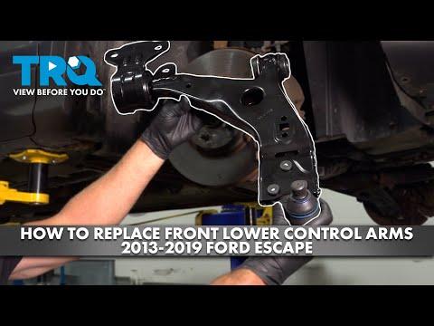


How to Replace Front Lower Control Arms on a 2013-2019 Ford Escape
Step-by-step instructions for both sides with tools, parts, torque specs, and safety tips for 2013, 2014, 2015, 2016, 2017, 2018, 2019
How to Replace Front Lower Control Arms on a 2013-2019 Ford Escape
Step-by-step instructions for both sides with tools, parts, torque specs, and safety tips for 2013, 2014, 2015, 2016, 2017, 2018, 2019


🔧 Escape - Front Lower Control Arm Replacement
Replace the complete front lower control-arm assemblies, including their bushings and ball joints. This is an intermediate suspension repair because the fasteners are tight and the arms must be torqued at normal ride height.
Assumption: These instructions cover both front lower control arms, not the rear suspension links.
Difficulty Level: Intermediate | Estimated Time: 3-5 hours for both sides
⚠️ Safety & Precautions
- ⚠️ Support your Escape with jack stands on solid, level ground. Never work beneath a vehicle held only by a jack.
- ⚠️ Disconnect the negative battery cable before starting to protect the electric power-steering system.
- ⚠️ Do not place a separator fork between the ball-joint boot and steering knuckle. It can tear the new boot.
- ⚠️ Use new locking nuts and any one-time-use bolts supplied or specified with the replacement arms.
- ⚠️ Tighten the control-arm bushing fasteners at normal ride height. Tightening them with the suspension hanging twists the rubber bushings and shortens their life.
- ⚠️ Obtain a four-wheel alignment immediately after the repair.
🔧 Required Tools
You'll need the following tools for this repair:
- 10mm socket
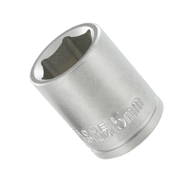
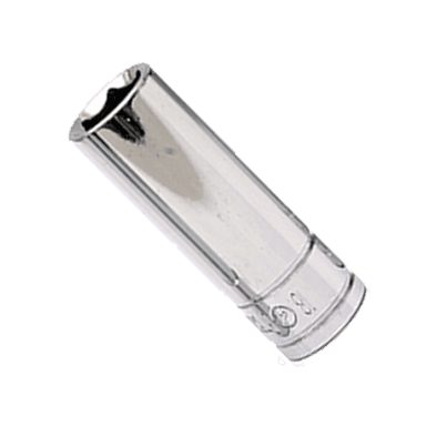
- 15mm six-point socket
- 18mm six-point socket
- 21mm six-point socket
- 19mm or 21mm wheel-nut socket
- 15mm combination wrench
- 18mm combination wrench
- 21mm combination wrench
- 1/2-inch drive breaker bar
- 1/2-inch drive ratchet
- 3/8-inch drive ratchet
- 1/2-inch drive torque wrench rated to 150 ft-lbs
- 6-inch socket extension
- Floor jack rated 2-ton minimum
- Jack stands rated 2-ton minimum
- Wheel chocks
- Large pry bar
- Ball-joint separator screw tool (specialty)
- 16-ounce hammer
- 3/8-inch punch
- Wire brush
- Paint marker
- Safety glasses
- Mechanic gloves
🔩 Required Parts
HowToo sells all the parts you need for this repair:
- Front left lower control arm and ball-joint assembly - Qty: 1
- Front right lower control arm and ball-joint assembly - Qty: 1
- Control-arm mounting hardware - Qty: 1 set per side
- Ball-joint locking hardware - Qty: 1 set per side
- Penetrating oil - Qty: 1 can
Complete assemblies are the smart buy for a first-time repair. Pressing individual bushings turns a straightforward job into a wrestling match with a hydraulic press.
📋 Before You Begin
- 📋 Park on level concrete, center the steering wheel, select Park, and apply the parking brake.
- 📋 Place wheel chocks securely behind both rear tires.
- 📋 Open the hood and let the vehicle sit with the ignition off and key removed.
- 📋 Use a 10mm socket to disconnect the negative battery cable. Isolate it so it cannot touch the terminal.
- 📋 Spray penetrating oil on the control-arm mounting bolts and ball-joint connection.
- 📋 Compare each new arm with the corresponding old arm before installation. Left and right arms are not interchangeable.
🔨 Step-by-Step Instructions
Follow these steps in order:
Step 1: Loosen the front wheel nuts
- Use the correct wheel-nut socket and a 1/2-inch breaker bar to loosen each front wheel nut about one-quarter turn.
- Do not remove the nuts while the tires are supporting the vehicle.
Step 2: Raise and support the front
- Use the floor jack at the approved front lifting point and raise your Escape.
- Position both jack stands under the approved reinforced support points.
- Lower the vehicle gently onto the stands and verify that it is stable before continuing.
Step 3: Remove the wheels
- Use the wheel-nut socket and 1/2-inch ratchet to remove the front wheel nuts.
- Remove both front wheels and slide one beneath each side as an additional safety measure.
Step 4: Mark and inspect the mounting points
- Use the paint marker to mark the positions of the control-arm fasteners and brackets.
- Inspect the steering knuckle, subframe mounting points, brake hose, ABS-sensor wire, and axle boot for damage.
- Use the wire brush to clean exposed threads.
Step 5: Disconnect the ball joint
- Use the appropriate 15mm or 18mm socket and matching wrench to remove the ball-joint locking fastener.
- Discard a removed locking nut or one-time-use fastener rather than reusing it.
- Use the punch and hammer only on the removable bolt, never on threaded ends that will be reused.
- Use the ball-joint separator screw tool to release the joint from the steering knuckle.
- Support the knuckle so its weight does not pull on the brake hose, ABS wire, or CV axle.
- Keep pressure away from the rubber boot.
Step 6: Remove the control-arm mounting fasteners
- Support the arm lightly with the floor jack.
- Use the 18mm or 21mm socket, breaker bar, and matching wrench to loosen the front bushing fastener.
- Use the appropriate socket and wrench to remove the rear bushing fastener or bracket bolts.
- Record each fastener's location and direction as it comes out.
- Do not loosen or remove the main subframe mounting bolts.
Step 7: Remove the old control arm
- Lower the floor jack slightly while controlling the arm by hand.
- Use the large pry bar against the metal arm or reinforced mounting area to work the bushings free.
- Remove the arm without pulling the steering knuckle outward.
- Compare the old and new arms side by side, including bolt-hole spacing, bushing orientation, ball-joint position, and ABS-wire clearance.
Step 8: Install the new control arm loosely
- Insert the new arm into the subframe mounting points.
- Install the bushing fasteners by hand. Do not fully tighten them yet.
- Use the floor jack to position the arm while guiding the ball joint into the steering knuckle.
- Install the new ball-joint hardware by hand and verify that the joint is fully seated.
Step 9: Tighten the ball-joint connection
- Use the correct socket, matching wrench, and torque wrench to tighten the ball-joint fastener.
- Torque to 63 Nm (46 ft-lbs).
- Confirm that the boot is not pinched, torn, or twisted. Ford-platform service information emphasizes using correct new locking hardware for this safety-critical connection. go-parts.com
Step 10: Load the suspension to normal ride height
- Position the floor jack beneath the sturdy outer portion of the new control arm.
- Raise the arm until the hub sits approximately at its normal ride-height relationship to the fender.
- Keep the vehicle's weight securely supported by the jack stand. The floor jack loads the suspension but does not replace the stand.
- This prevents the rubber bushings from being locked in a twisted position. go-parts.com
Step 11: Torque the control-arm bushing fasteners
- Use the 18mm or 21mm socket, matching wrench, and torque wrench while the suspension remains loaded.
- Torque the front bushing bolt to 115 Nm (85 ft-lbs).
- Torque the rear bushing fastener to 149 Nm (110 ft-lbs).
- Use the hardware instructions supplied with the replacement arm if they specify a different torque or an additional angle-tightening step.
- Never substitute an impact wrench for the final torque-wrench tightening. Suspension bolts aren't the place for “that feels tight enough.” go-parts.com
Step 12: Repeat on the opposite side
- Use the same tools and procedure to replace the other front lower control arm.
- Replace one side completely before disassembling the other side so the assembled side remains a reference.
Step 13: Reinstall the wheels
- Clean the wheel-to-hub contact surfaces with the wire brush.
- Install each wheel and start every nut by hand.
- Use the wheel-nut socket and ratchet to snug the nuts in a star pattern.
- Use the floor jack to raise the vehicle, remove the jack stands, and lower it until the tires touch the ground.
- Use the torque wrench and wheel-nut socket to tighten in a star pattern to 135 Nm (100 ft-lbs). go-parts.com
Step 14: Reconnect the battery
- Use the 10mm socket to reconnect and secure the negative battery terminal.
- Start the engine and turn the steering wheel slowly from center toward each side, without forcing it against the stops.
✅ After Repair
- ✅ Press down firmly over each front corner and listen for clunks or metallic movement.
- ✅ Check that both ball-joint boots remain seated and undamaged.
- ✅ Verify that the brake hoses, ABS wires, and CV boots are clear of the new arms.
- ✅ Drive slowly in a safe area and check steering response, braking stability, and unusual noises.
- ✅ Arrange a four-wheel alignment immediately. Replacing an arm can change toe and other suspension angles. go-parts.com
- ✅ Recheck the wheel-nut torque after approximately 50 miles.
- ✅ Stop driving if the steering feels loose, the vehicle pulls sharply, or you hear repeated knocking.
💰 DIY vs Shop Cost
Shop Cost: $750-$1,600 for both sides, including parts, labor, and alignment
DIY Cost: $285-$550 for both arms, hardware, supplies, and alignment
You Save: Approximately $465-$1,050 by doing it yourself!
Shop labor rates vary but commonly run $100-$180/hour. This repair takes a shop approximately 3-5 labor hours for both sides.
🎯 Ready to get started?
HowToo makes it easy: same-day/2-day shipping on every part, plus all the tools and specialty tools you need! Check out the parts and tools sections below to add everything to your cart.