



How to Replace Front Lower Ball Joints on a 2019-2024 Subaru Ascent
Step-by-step suspension repair guide with required tools, parts, torque specs, and safety tips for 2019, 2020, 2021, 2022, 2023, 2024
How to Replace Front Lower Ball Joints on a 2019-2024 Subaru Ascent
Step-by-step suspension repair guide with required tools, parts, torque specs, and safety tips for 2019, 2020, 2021, 2022, 2023, 2024


🔧 Ascent - Front Lower Ball Joint Replacement
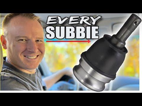
This is an advanced suspension repair. Each front ball joint connects the lower control arm to the steering knuckle, allowing the wheel to steer while the suspension moves.
The joint is secured in the knuckle by a horizontal pinch bolt and attached to the control arm with a castle nut. Corrosion can make removal considerably harder, so don't force or heat the aluminum knuckle.
Difficulty Level: Advanced | Estimated Time: 2-4 hours per side
Assumption: These instructions cover one front lower ball joint on a stock Ascent.
⚠️ Safety & Precautions
- ⚠️ Never work under your Ascent while it is supported only by a jack.
- ⚠️ Support the vehicle with correctly rated jack stands on solid, level ground.
- ⚠️ A loose ball-joint fastener can allow the suspension to separate and cause loss of control.
- ⚠️ Do not damage, stretch, or support the knuckle by the brake hose or ABS sensor wire.
- ⚠️ Do not strike the threaded ball-joint stud directly with a steel hammer.
- ⚠️ Do not apply grease or anti-seize to the tapered ball-joint stud.
- ⚠️ Do not use an open flame near the brake hose, CV boot, wheel-speed sensor, or ball-joint boot.
- ⚠️ Replace a cracked, heavily corroded, or distorted steering knuckle instead of spreading it aggressively.
- 🔋 Battery disconnection is not normally required for this mechanical repair.
🔧 Required Tools
You'll need the following tools for this repair:
- 19mm wheel-lug socket
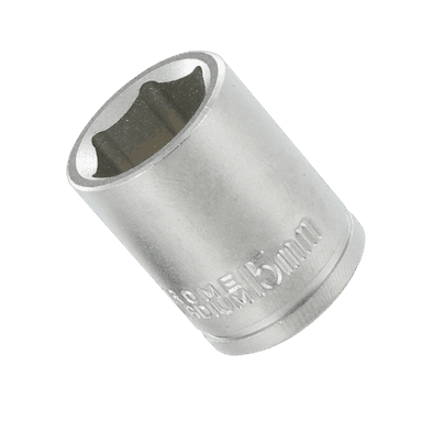
- 14mm six-point socket
- 22mm six-point socket
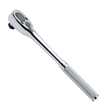
- 3/8-inch drive ratchet
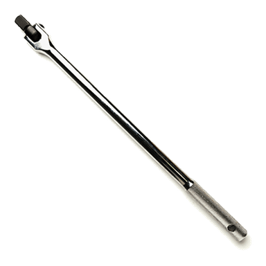
- 1/2-inch drive breaker bar
- 1/2-inch drive torque wrench rated to 150 N·m
- 6-inch socket extension
- Needle-nose pliers
- Ball-joint separator tool (specialty)
- Subaru-style ball-joint removal tool (specialty)
- Small flat-blade screwdriver
- 12-inch pry bar
- Brass drift punch
- 24-ounce ball-peen hammer
- Small wire brush
- Floor jack rated 3-ton minimum
- Jack stands rated 3-ton minimum
- Wheel chocks
- Mechanic's gloves
- Safety glasses
🔩 Required Parts
HowToo sells all the parts you need for this repair:
- Front lower ball joint - Qty: 1 per side
- New ball-joint castle nut - Qty: 1 per side
- New ball-joint cotter pin - Qty: 1 per side
- New ball-joint pinch bolt and locking nut - Qty: 1 per side
- Penetrating oil - Qty: 1 can
- Brake parts cleaner - Qty: 1 can
Replace both sides if both joints have looseness or torn boots. Otherwise, replacing only the failed side is acceptable after inspecting the opposite side.
📋 Before You Begin
- 🅿️ Park on level pavement, select Park, engage the parking brake, and switch off the ignition.
- Place wheel chocks securely behind both rear wheels.
- Confirm the replacement joint includes an undamaged boot, castle nut, and cotter pin.
- Spray penetrating oil onto the ball-joint pinch bolt and castle-nut threads. Allow it to soak.
- No infotainment service mode, electronic parking-brake mode, or scan-tool command is required.
- Arrange a professional alignment inspection after the repair, especially if looseness caused abnormal tire wear.
🔨 Step-by-Step Instructions
Follow these steps in order:
Step 1: Loosen the Wheel Nuts
- Use the 19mm wheel-lug socket and 1/2-inch breaker bar to loosen each front wheel nut approximately one-quarter turn.
- Do not remove the nuts while the tire is supporting the vehicle.
Step 2: Raise and Support the Vehicle
- Use the 3-ton floor jack at the approved front-center lifting point.
- Position the 3-ton jack stands beneath the approved side support points.
- Lower your Ascent onto the stands and gently shake the body to confirm stability.
- Keep the floor jack lightly touching the lifting point as secondary support without carrying the vehicle's weight.
Step 3: Remove the Front Wheel
- Use the 19mm wheel-lug socket and 3/8-inch ratchet to remove the wheel nuts.
- Remove the wheel and slide it under the rocker area as additional protection.
Step 4: Inspect the Work Area
- Locate the ball joint beneath the steering knuckle.
- Identify the horizontal pinch bolt where the ball joint enters the knuckle.
- Identify the castle nut and cotter pin underneath the lower control arm.
- Check the CV boot, brake hose, and ABS sensor wire. Move slowly around all three.
Step 5: Remove the Cotter Pin
- Use the needle-nose pliers and small flat-blade screwdriver to straighten and remove the cotter pin.
- Discard the old cotter pin. Never reinstall it.
- If it breaks, use the brass drift punch and 24-ounce hammer to push the remaining piece through the stud.
Step 6: Loosen the Castle Nut
- Use the 22mm six-point socket, extension, and breaker bar to loosen the castle nut.
- Leave the nut threaded onto the end of the stud by several turns. It will protect the threads while the taper is separated.
- The loose nut also catches the control arm.
Step 7: Separate the Stud from the Control Arm
- Fit the ball-joint separator tool between the joint and control arm without pinching the rubber boot.
- Tighten the separator gradually until the tapered stud releases from the control arm.
- Remove the loosened castle nut with the 22mm socket.
- Use the 12-inch pry bar carefully to lower the control arm away from the stud.
- Do not pull the knuckle outward far enough to overextend the inner CV joint.
Step 8: Remove the Knuckle Pinch Bolt
- Use the 14mm six-point socket, extension, and breaker bar to remove the horizontal pinch bolt.
- Use the brass drift punch and hammer only if the released bolt needs gentle assistance.
- Stop if the bolt begins twisting instead of turning. A broken pinch bolt can turn this into a steering-knuckle replacement.
Step 9: Extract the Old Ball Joint
- Attach the Subaru-style ball-joint removal tool to the joint according to the tool manufacturer's directions.
- Use the appropriate socket and ratchet supplied or specified with that tool to draw the joint straight out of the knuckle.
- Do not hammer against the aluminum knuckle or drive a large wedge deeply into its clamp opening.
- Remove the old joint and inspect the knuckle bore for cracks, heavy corrosion, or deformation.
Step 10: Clean the Knuckle Bore
- Use the small wire brush to remove loose rust and debris from the bore.
- Use brake parts cleaner to flush away residue, then allow the bore to dry.
- Keep cleaner away from the new joint's rubber boot.
- Do not remove metal or enlarge the bore with a rotary grinding tool.
Step 11: Install the New Ball Joint
- Position the joint so its retaining groove aligns with the pinch-bolt passage.
- Use the Subaru-style ball-joint removal tool in installation configuration to pull the joint fully into the knuckle.
- Confirm the joint's shoulder is seated evenly against the bottom of the knuckle.
- Pass the new pinch bolt through by hand. If it will not pass freely, the joint is not correctly aligned or fully seated.
Step 12: Tighten the Pinch Bolt
- Install the new locking nut on the new pinch bolt.
- Use the 14mm socket and torque wrench to tighten the fastener.
- Torque to 50 N·m (37 ft-lbs). Subaru service information uses this value for its front ball-joint knuckle clamp design. subaruport.ru)
Step 13: Connect the Control Arm
- Use the 12-inch pry bar carefully to lower the control arm enough to guide the new stud into its hole.
- Make sure the tapered stud and control-arm hole are clean and dry.
- Thread the new castle nut onto the stud by hand.
- Use the 22mm socket and torque wrench to tighten the nut.
- Torque to 39 N·m (29 ft-lbs). If the cotter-pin hole does not align, tighten the nut farther, up to 60 degrees. Never loosen it for alignment. subaruport.ru)
- Insert the new cotter pin with the needle-nose pliers and bend its legs securely around the nut.
Step 14: Recheck the Installation
- Confirm the joint is fully seated and the pinch bolt passes through its retaining groove.
- Confirm the rubber boot is not pinched, cut, or twisted.
- Confirm the castle nut is fully seated and the new cotter pin is locked in place.
- Check that the brake hose and ABS sensor wire remain correctly routed.
Step 15: Reinstall the Wheel
- Install the wheel and start every wheel nut by hand.
- Use the 19mm wheel-lug socket and ratchet to snug the nuts in a star pattern.
- Raise your Ascent with the 3-ton floor jack, remove the jack stands, and lower the tire until it just contacts the ground.
- Use the 19mm socket and torque wrench to tighten the wheel nuts in a star pattern.
- Torque to 120 N·m (89 ft-lbs). sulegacy.com
✅ After Repair
- 🔍 Turn the steering slowly from side to side and listen for rubbing, popping, or binding.
- Press the brake pedal before moving to confirm normal pedal feel.
- Drive slowly in a safe area and verify that steering response is normal.
- Stop immediately if you hear clunking or notice wandering, pulling, or an off-center steering wheel.
- Inspect the pinch bolt, castle nut, cotter pin, boot, brake hose, and ABS wire after the road test.
- Have the alignment checked. Ball-joint replacement normally doesn't provide an adjustment, but previous joint wear may have affected tire wear or steering geometry.
- Recheck wheel-nut torque after approximately 50-100 miles.
💰 DIY vs Shop Cost
Shop Cost: $400-$800 per side, including parts, labor, and alignment
DIY Cost: $50-$250 per side, excluding tools and alignment
You Save: Approximately $200-$500 per side by doing it yourself.
Shop labor rates vary but typically run $100-$150/hour. This repair takes a shop approximately 1.5-3 hours per side, depending heavily on corrosion.
🎯 Ready to get started?
HowToo makes it easy: same-day/2-day shipping on every part, plus all the tools and specialty tools you need! Check out the parts and tools sections below to add everything to your cart.