

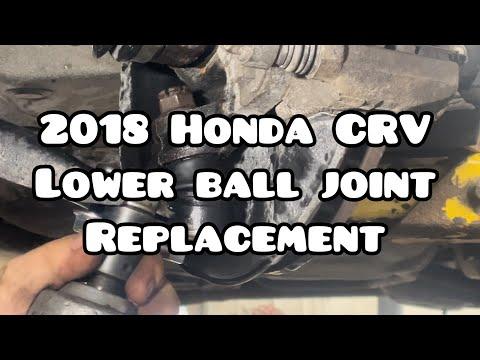


How to Replace Front Lower Ball Joints on a 2017-2022 Honda CR-V
Step-by-step knuckle removal and press-fit guide with tools, parts, torque specs, and safety tips for 2017, 2018, 2019, 2020, 2021, 2022
How to Replace Front Lower Ball Joints on a 2017-2022 Honda CR-V
Step-by-step knuckle removal and press-fit guide with tools, parts, torque specs, and safety tips for 2017, 2018, 2019, 2020, 2021, 2022


🔧 CR-V - Front Lower Ball Joint Replacement
This procedure replaces a worn front lower ball joint by removing the steering knuckle and pressing the joint out of it. A hydraulic press or correctly sized ball-joint press adapters are required; improper support can crack the aluminum steering knuckle.
Assumption: This guide covers one front lower ball joint; repeat the procedure on the opposite side if needed.
Difficulty Level: Advanced | Estimated Time: 4-6 hours per side
⚠️ Safety & Precautions
- ⚠️ Support your CR-V with jack stands on its reinforced lift points. Never work beneath a vehicle supported only by a jack.
- ⚠️ Wear safety glasses while separating or pressing the ball joint. Pressed components can release suddenly.
- ⚠️ Do not pull outward on the CV axle. Separating the inner joint can damage its internal rollers.
- ⚠️ Do not allow the brake caliper to hang from its hose.
- ⚠️ Protect the wheel-speed sensor and wiring. Damage can disable ABS and stability control.
- ⚠️ Support the steering knuckle directly around the ball-joint bore during pressing. Do not load the wheel bearing or thin casting edges.
- ⚠️ The battery does not need to be disconnected.
- ⚠️ A professional wheel alignment is required after this repair.
🔧 Required Tools
You'll need the following tools for this repair:
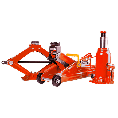
- 3-ton floor jack
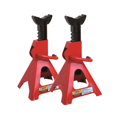
- 3-ton jack stands
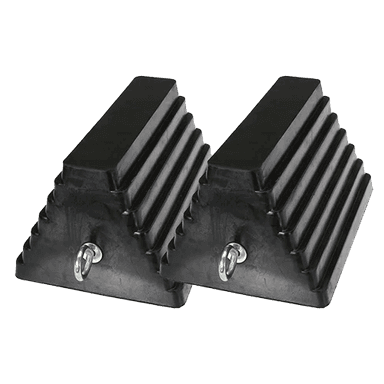
- Wheel chocks
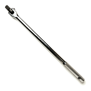
- 1/2-inch drive breaker bar
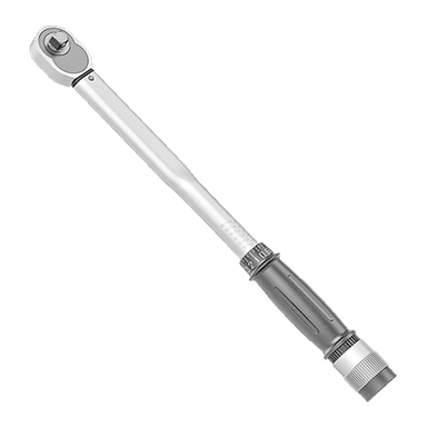
- 1/2-inch drive torque wrench rated 20-250 ft-lbs
- 3/8-inch drive torque wrench rated 5-80 ft-lbs
- 19mm impact socket
- 36mm axle-nut socket
- 12mm socket
- 14mm socket
- 17mm socket
- 19mm socket
- 22mm socket
- 14mm combination wrench
- 17mm combination wrench
- 19mm combination wrench
- 6-inch socket extension
- Flat-blade screwdriver
- Needle-nose pliers
- External snap-ring pliers
- Ball-joint separator (specialty)
- Tie-rod-end puller (specialty)
- Ball-joint press with Honda-size adapters (specialty)
- Hydraulic shop press rated 12-ton minimum (specialty)
- Steering-knuckle support plates (specialty)
- CV axle pusher (specialty)
- Brass drift punch
- 32-ounce ball-peen hammer
- Medium pry bar
- Caliper hanger hook
- Paint marker
- Wire brush
- Brake-parts cleaner
- Clean shop towels
- Nitrile mechanic gloves
- Safety glasses
🔩 Required Parts
HowToo sells all the parts you need for this repair:
- Front lower ball joint - Qty: 1 per side
- Lower ball-joint snap ring - Qty: 1 per side
- Lower ball-joint cotter pin - Qty: 1 per side
- Outer tie-rod-end cotter pin - Qty: 1 per side
- Front axle spindle nut - Qty: 1 per side
- Front strut-to-knuckle self-locking nuts - Qty: 2 per side
- High-temperature wheel-bearing grease - Qty: 1 small tube
Ball joints do not have to be replaced in pairs, but inspect the opposite side for looseness or a torn dust boot.
📋 Before You Begin
- 📋 Park your CR-V on level, solid ground. Place the transmission in Park and apply the parking brake.
- 📋 Chock both rear wheels before lifting the front.
- 📋 Loosen the axle spindle nut and wheel nuts while the tire is still touching the ground.
- 📋 A snap ring is a spring-steel retaining ring that locks the ball joint into the steering knuckle.
- 📋 A ball-joint separator pushes the tapered stud out without striking or deforming it.
- 📋 Arrange professional press service before starting if you do not have a hydraulic press and exact-size adapters.
🔨 Step-by-Step Instructions
Follow these steps in order:
Step 1: Loosen the axle nut and wheel nuts
- Use the flat-blade screwdriver to lift the staked portion of the axle spindle nut out of the axle groove.
- Use the 36mm axle-nut socket and 1/2-inch breaker bar to loosen the spindle nut. Do not remove it yet.
- Use the 19mm impact socket and breaker bar to loosen each wheel nut approximately one-half turn.
Step 2: Raise and support the vehicle
- Use the 3-ton floor jack at the front center lifting point.
- Place the 3-ton jack stands beneath the reinforced front side lift points.
- Lower the vehicle onto the stands and gently push the body to confirm it is stable.
- Use the 19mm impact socket to remove the wheel nuts and wheel.
Step 3: Remove the brake caliper and rotor
- Use the 17mm socket to remove the two caliper-bracket bolts from the steering knuckle.
- Lift off the complete caliper and bracket. Use the caliper hanger hook to support it from the strut spring.
- Use the 12mm socket to remove the rotor retaining screws if fitted. Remove the brake rotor by hand.
- If the rotor is stuck, thread suitable 8mm rotor-removal bolts evenly into its extraction holes.
- Never press the brake pedal now.
Step 4: Free the wheel-speed sensor harness
- Use the 12mm socket to remove the wheel-speed sensor wire brackets from the knuckle and strut.
- If clearance requires sensor removal, use the 10mm-equivalent fastener socket supplied for the sensor bolt and gently twist the sensor free by hand.
- Do not pry against the sensor tip or pull on its wire.
- On installation, tighten small wheel-speed harness and sensor fasteners only to their original seated position; do not overtighten these small bolts.
Step 5: Separate the outer tie-rod end
- Use needle-nose pliers to remove the tie-rod cotter pin.
- Use the 17mm socket to remove the castle nut.
- Install the tie-rod-end puller and tighten it with the appropriate 17mm or 19mm wrench until the tapered stud releases.
- Do not strike the threaded stud.
Step 6: Separate the lower ball joint from the control arm
- Use needle-nose pliers to remove the lower ball-joint cotter pin.
- Use the 19mm socket to loosen and remove the ball-joint castle nut.
- Position the ball-joint separator between the lower control arm and steering knuckle.
- Tighten the separator with the 19mm or 22mm wrench until the taper releases.
- Use the medium pry bar only as needed to guide the control arm down. Do not damage the rubber CV axle boot.
Step 7: Disconnect the strut from the steering knuckle
- Use the paint marker to trace the strut-to-knuckle position. This helps keep alignment close enough for the drive to an alignment shop.
- Support the knuckle with the 3-ton floor jack.
- Use the 22mm socket and 22mm wrench to remove the two strut-to-knuckle nuts and bolts.
- Keep the knuckle supported so it cannot pull on the axle, brake hose, or sensor wire.
Step 8: Remove the steering knuckle
- Remove the loosened spindle nut with the 36mm axle-nut socket.
- Install the CV axle pusher over the hub and press the axle splines inward.
- If needed, use the brass drift punch and 32-ounce hammer lightly on the axle end. Never hit the axle threads directly with a steel hammer.
- Guide the axle out of the hub while supporting both the knuckle and axle.
- Remove the steering knuckle from your CR-V.
Step 9: Remove the old ball joint
- Use the wire brush and brake-parts cleaner to clean dirt from the ball-joint area.
- Use external snap-ring pliers to remove the ball-joint snap ring.
- Place the knuckle on the steering-knuckle support plates with support immediately around the ball-joint bore.
- Use the hydraulic shop press and a correctly sized press adapter to push the old ball joint out in its removal direction.
- Stop immediately if the knuckle tilts, bends, or contacts the wheel bearing.
Step 10: Press in the new ball joint
- Use brake-parts cleaner and a clean shop towel to clean the knuckle bore. Do not enlarge it with abrasive tools.
- Apply only a very thin film of high-temperature wheel-bearing grease to the outside metal shell of the new joint.
- Orient the replacement joint exactly as specified by its installation marks and dust-boot position.
- Use the hydraulic shop press and Honda-size adapter to press only against the joint's outer metal flange.
- Press the joint fully against its machined seat. Do not press against the stud or rubber boot.
- Use external snap-ring pliers to install the new snap ring. Confirm it is completely seated around the entire groove.
- A half-seated snap ring is unsafe.
Step 11: Reinstall the steering knuckle
- Guide the CV axle splines into the hub by hand. Do not hammer the axle into the hub.
- Install the new spindle nut finger-tight with the 36mm axle-nut socket.
- Position the knuckle in the strut and install the two bolts with new self-locking nuts.
- Align the paint marks, then use the 22mm socket, 22mm wrench, and torque wrench to tighten both strut-to-knuckle fasteners to Torque to 157 Nm (116 ft-lbs).
Step 12: Connect the ball joint and tie-rod end
- Use the medium pry bar carefully to position the control arm beneath the new ball-joint stud.
- Install the ball-joint castle nut with the 19mm socket and tighten to Torque to 54 Nm (40 ft-lbs).
- If the cotter-pin holes do not align, tighten the nut slightly farther. Never loosen it to align the holes.
- Use needle-nose pliers to install and bend the new ball-joint cotter pin.
- Insert the tie-rod-end stud into the knuckle and install its castle nut with the 17mm socket.
- Tighten the tie-rod-end nut to Torque to 44 Nm (33 ft-lbs).
- Tighten only enough farther to align the holes, then use needle-nose pliers to install a new cotter pin.
Step 13: Reinstall the wheel-speed harness and brakes
- Route the wheel-speed sensor wire through every original bracket without twists or contact with the axle.
- Use the 12mm socket to reinstall the harness brackets securely without crushing them.
- Clean the brake rotor with brake-parts cleaner and a clean shop towel, then reinstall it.
- Position the caliper assembly over the rotor without twisting the brake hose.
- Use the 17mm socket and torque wrench to tighten the caliper-bracket bolts to Torque to 137 Nm (101 ft-lbs).
Step 14: Install the wheel and tighten the axle nut
- Install the wheel and hand-start all five wheel nuts.
- Use the 19mm impact socket to snug the wheel nuts in a star pattern. Do not fully torque them while raised.
- Use the 3-ton floor jack to lift your CR-V, remove the jack stands, and lower the tire until it just contacts the ground.
- Use the 36mm axle-nut socket and torque wrench to tighten the new spindle nut to Torque to 245 Nm (181 ft-lbs).
- Use the brass drift punch and 32-ounce hammer to stake the edge of the spindle nut firmly into the axle groove.
- Lower the vehicle completely.
- Use the 19mm impact socket and torque wrench to tighten the wheel nuts in a star pattern to Torque to 108 Nm (80 ft-lbs).
✅ After Repair
- ✅ Before moving, press the brake pedal several times until it feels firm.
- ✅ Start your CR-V and confirm that the ABS and stability-control warning lights turn off normally.
- ✅ Turn the steering slowly from side to side and listen for rubbing, clicking, or binding.
- ✅ Drive slowly in a safe area. Confirm normal steering response and braking before reaching road speed.
- ✅ Arrange a four-wheel alignment immediately. Suspension separation can change toe and camber.
- ✅ Recheck the ball-joint boot, cotter pins, sensor-wire routing, axle-nut stake, and wheel-nut torque after the test drive.
- ✅ Do not drive if there is looseness, steering pull, clicking, an ABS warning, or a damaged dust boot.
💰 DIY vs Shop Cost
Shop Cost: ₹18,000-₹35,000 per side (parts, pressing, labor, and alignment)
DIY Cost: ₹5,000-₹12,000 per side (parts and alignment only)
You Save: ₹10,000-₹23,000 per side by doing it yourself!
Local labor rates and imported-part availability vary. A shop typically needs approximately 3-5 hours per side, including press work and alignment.
🎯 Ready to get started?
HowToo makes it easy: same-day/2-day shipping on every part, plus all the tools and specialty tools you need! Check out the parts and tools sections below to add everything to your cart.