

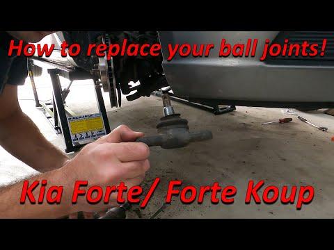



How to Replace Front Lower Ball Joints on a 2014-2018 Kia Forte
Step-by-step control arm replacement with required tools, torque specs, and safety tips for 2014, 2015, 2016, 2017, 2018
How to Replace Front Lower Ball Joints on a 2014-2018 Kia Forte
Step-by-step control arm replacement with required tools, torque specs, and safety tips for 2014, 2015, 2016, 2017, 2018


🔧 Forte - Front Lower Ball Joint Replacement
Assumption: This procedure covers both front lower ball joints on your Forte. The ball joints are built into the lower control arms, so replace the complete control-arm assemblies rather than pressing out the joints.
Each control arm connects the steering knuckle to the front subframe and lets the suspension move safely. A worn ball joint can cause clunking, wandering steering, uneven tire wear, or separation of the wheel from the suspension.
Difficulty Level: Advanced | Estimated Time: 3-5 hours
⚠️ Safety & Precautions
- ⚠️ Do not drive your Forte if the ball joint has excessive movement or appears ready to separate.
- ⚠️ Support the vehicle with jack stands. Never work beneath a vehicle supported only by a floor jack.
- ⚠️ Keep the steering knuckle supported so the brake hose and ABS sensor wire are not stretched.
- ⚠️ A ball-joint separator can release the tapered stud suddenly. Wear eye protection and keep hands clear.
- ⚠️ Final-tighten the control-arm pivot bolts at normal ride height. Tightening them with the suspension hanging can damage the rubber bushings.
- ⚠️ Do not use heat near the ball joint, rubber bushings, brake hose, or wheel-speed sensor wiring.
- 🔋 Battery disconnection is not required.
🔧 Required Tools
You'll need the following tools for this repair:
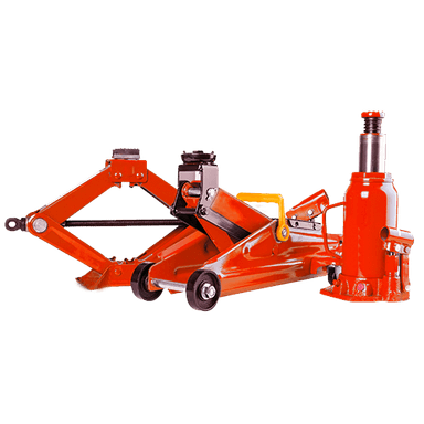
- 3-ton floor jack
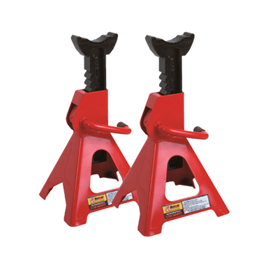
- 3-ton jack stands
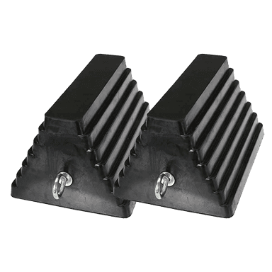
- Rubber wheel chocks
- Safety glasses
- Mechanic gloves
- 1/2-inch drive breaker bar
- 1/2-inch drive ratchet
- 3/8-inch drive ratchet
- 1/2-inch drive torque wrench (30-250 Nm)
- 21mm deep impact socket
- 19mm six-point socket
- 17mm six-point socket
- 19mm combination wrench
- 17mm combination wrench
- 6mm hex-bit socket
- Ball-joint separator (specialty)
- Small needle-nose pliers
- 12-inch adjustable pry bar
- 16-ounce ball-peen hammer
- Brass wire brush
- Paint marker
- Penetrating oil
- Medium-strength threadlocker
- Hydraulic jack with rubber saddle pad
🔩 Required Parts
HowToo sells all the parts you need for this repair:
- Front lower control arm with ball joint, left - Qty: 1
- Front lower control arm with ball joint, right - Qty: 1
- Front lower ball-joint self-locking nuts - Qty: 2
- Front lower control-arm pivot bolts and self-locking nuts - Qty: 1 set
Replace in pairs: Replacing both front control arms keeps ball-joint and bushing condition consistent from side to side.
📋 Before You Begin
- 🅿️ Park your Forte on firm, level ground. Center the steering wheel, select Park, apply the parking brake, and switch off the ignition.
- 🛞 Place rubber wheel chocks securely behind both rear tires.
- 📏 Arrange a four-wheel alignment immediately after the repair. Replacing control arms can alter wheel alignment.
- 🧰 Spray penetrating oil on the ball-joint nuts and control-arm fasteners. Allow it to soak before loosening them.
- 📱 No infotainment service mode, scan-tool command, EPB retraction, battery registration, or ADAS calibration mode is required.
- 🔩 Check replacement arms before lifting the vehicle. The ball-joint stud, bushings, and mounting points must match the removed assemblies.
🔨 Step-by-Step Instructions
Follow these steps in order:
Step 1: Loosen the front wheel nuts
- Use the 21mm deep impact socket and 1/2-inch drive breaker bar to loosen each front wheel nut about one-quarter turn.
- Do not remove the nuts while the vehicle is resting on the ground.
Step 2: Raise and support the vehicle
- Use the 3-ton floor jack beneath the reinforced front-center lifting point to raise your Forte.
- Position the 3-ton jack stands beneath the left and right reinforced pinch-weld support points.
- Lower the vehicle onto the stands, then gently push the body to confirm it is stable.
- Leave the 3-ton floor jack lightly touching the front lifting point as secondary support.
Step 3: Remove both front wheels
- Use the 21mm deep impact socket and 1/2-inch drive ratchet to remove the wheel nuts.
- Lift off both wheels and place them flat away from the work area.
Step 4: Support the steering knuckle
- Place the hydraulic jack with rubber saddle pad beneath the outer end of the control arm.
- Raise it only enough to support the assembly. Do not lift your Forte off the jack stand.
- Inspect the brake hose and ABS wire so neither can become stretched.
Step 5: Disconnect the stabilizer link if it blocks removal
- If the stabilizer link attaches to or obstructs the control arm, use the 17mm combination wrench and 6mm hex-bit socket to remove its lower nut.
- The stabilizer link joins the left and right suspension through the anti-roll bar.
- Move the link aside without damaging its rubber boot.
Step 6: Remove the ball-joint nut
- Use the brass wire brush to clean exposed threads.
- If a cotter pin is fitted, straighten and remove it with the small needle-nose pliers.
- Use the 19mm six-point socket and 1/2-inch drive breaker bar to loosen and remove the ball-joint nut.
- Keep the hydraulic jack with rubber saddle pad beneath the arm while working.
Step 7: Separate the ball joint from the knuckle
- Fit the ball-joint separator between the steering knuckle and ball-joint stud, then tighten the separator until the tapered stud releases.
- A tapered stud is a cone-shaped shaft that locks tightly inside the knuckle.
- If needed, tap the side of the knuckle boss with the 16-ounce ball-peen hammer. Do not strike the stud, boot, brake rotor, or aluminum components.
- Lower the hydraulic jack with rubber saddle pad slowly, then guide the stud out with the 12-inch adjustable pry bar.
- Expect a sharp pop when it releases.
Step 8: Mark and loosen the control-arm fasteners
- Use the paint marker to mark the orientation of the front and rear control-arm fasteners.
- Use the correctly fitting 17mm or 19mm six-point socket, matching combination wrench, and 1/2-inch drive breaker bar to loosen the front pivot bolt and rear bushing fastener.
- Use only the socket that fits fully and tightly. Fastener head sizes can differ between original and replacement hardware.
Step 9: Remove the old control arm
- Use the 17mm or 19mm six-point socket and matching combination wrench to remove the pivot fasteners.
- Support the arm with one hand, then use the 12-inch adjustable pry bar to ease the bushings from the subframe brackets.
- Remove the complete control arm and ball-joint assembly.
- Do not pry against a brake line, steering rack boot, or subframe seam.
Step 10: Compare the replacement arm
- Place the old and new arms side by side and visually compare their length, mounting sleeves, ball-joint stud, and left- or right-side shape.
- Use the brass wire brush to remove loose rust and dirt from the mounting brackets.
- Do not apply grease to the ball-joint taper or the corresponding hole in the steering knuckle.
Step 11: Install the replacement control arm
- Position the replacement arm in the subframe brackets by hand.
- Insert the new pivot bolts and nuts in their original orientation. Use the 17mm or 19mm six-point socket and matching combination wrench to make them snug only.
- Do not final-tighten the rubber-bushing fasteners while the suspension is hanging.
- Guide the ball-joint stud into the steering knuckle using the hydraulic jack with rubber saddle pad.
Step 12: Tighten the ball-joint connection
- Install a new self-locking ball-joint nut.
- Use the 19mm six-point socket and 1/2-inch drive torque wrench to tighten the ball-joint nut to 59-71 Nm (44-52 ft-lbs).
- If the replacement design uses a castellated nut, continue tightening only enough to align the next slot, then install its new cotter pin with the small needle-nose pliers. Never loosen the nut to align it.
Step 13: Reconnect the stabilizer link
- If removed, insert the link into its mounting point.
- Apply a small amount of medium-strength threadlocker only if the replacement-link instructions permit it.
- Use the 17mm combination wrench, 6mm hex-bit socket, and 1/2-inch drive torque wrench to tighten the stabilizer-link nut to 98-118 Nm (72-87 ft-lbs).
- Keep the link boot from twisting while tightening.
Step 14: Repeat on the opposite side
- Repeat Steps 4 through 13 using the same listed tools.
- Do not interchange the left and right control arms.
Step 15: Load the suspension to normal ride height
- Use the hydraulic jack with rubber saddle pad beneath the outer end of each control arm to raise the suspension.
- Use the paint marker reference and raise the arm until the hub-to-fender position approximates normal ride height.
- Confirm your Forte remains firmly supported by the 3-ton jack stands.
Step 16: Final-tighten the control-arm pivots
- Use the appropriate 17mm or 19mm six-point socket, matching combination wrench, and 1/2-inch drive torque wrench.
- Tighten the front control-arm pivot fastener to 98-118 Nm (72-87 ft-lbs).
- Tighten the rear control-arm bushing fastener to 157-177 Nm (116-131 ft-lbs).
- Slowly lower the hydraulic jack with rubber saddle pad after both fasteners are tightened.
Step 17: Install the front wheels
- Fit each wheel and hand-start all wheel nuts.
- Use the 21mm deep impact socket and 1/2-inch drive ratchet to snug the nuts in a star pattern.
- Use the 3-ton floor jack to raise your Forte, remove the 3-ton jack stands, and lower the tires to the ground.
- Use the 21mm deep impact socket and 1/2-inch drive torque wrench to tighten the wheel nuts in a star pattern to 88-108 Nm (65-80 ft-lbs).
✅ After Repair
- 🔍 Check that every fastener is secure and that no brake hose or ABS wire is twisted, pinched, or stretched.
- 🛞 Turn the steering wheel slowly from lock to lock and listen for contact, binding, or popping.
- 🚗 Test-drive at walking speed in a safe area first. Confirm the steering responds normally and no clunking is present.
- 📏 Have a four-wheel alignment performed before normal driving to prevent poor handling and tire wear.
- 🔩 Recheck wheel-nut torque after approximately 80-160 km (50-100 miles).
- 🛑 Stop driving immediately if the steering wheel is badly off-center, the vehicle pulls sharply, or a metallic clunk remains.
💰 DIY vs Shop Cost
Shop Cost: $650-$1,100 (parts + labor)
DIY Cost: $220-$450 (parts only)
You Save: $430-$650 by doing it yourself!
Shop labor rates vary but typically run $100-$150/hour. This repair takes a shop approximately 2.5-4 hours, plus alignment.
🎯 Ready to get started?
HowToo makes it easy: same-day/2-day shipping on every part, plus all the tools and specialty tools you need! Check out the parts and tools sections below to add everything to your cart.