

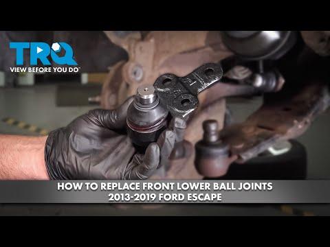


How to Replace Front Lower Ball Joints on a 2013-2019 Ford Escape
Step-by-step control arm replacement with required tools, parts, torque specs, and safety tips for 2013, 2014, 2015, 2016, 2017, 2018, 2019
How to Replace Front Lower Ball Joints on a 2013-2019 Ford Escape
Step-by-step control arm replacement with required tools, parts, torque specs, and safety tips for 2013, 2014, 2015, 2016, 2017, 2018, 2019


🔧 Escape - Front Lower Ball Joint Replacement
For a beginner, replace each lower control arm with its ball joint already installed. It costs more than pressing in separate joints, but it avoids a hydraulic press and renews the control-arm bushings at the same time. The matched control arms and standalone ball joints are now displayed in the parts sidebar.
Assumption: This procedure covers the front lower ball joints. Published specifications vary slightly by drivetrain, so verify the new part instructions before final tightening.
Difficulty Level: Intermediate | Estimated Time: 3-5 hours for both sides
⚠️ Safety & Precautions
- ⚠️ Never work underneath your Escape while it’s supported only by a floor jack.
- ⚠️ A badly worn ball joint can separate and cause loss of steering. Don’t drive the vehicle if the wheel visibly shifts or the joint is coming apart.
- ⚠️ Support the steering knuckle so it can’t hang from the brake hose or wheel-speed sensor wire.
- ⚠️ Don’t hammer, spread, or pry open the steering-knuckle slot. It can permanently damage the knuckle.
- ⚠️ Replace removed torque-sensitive control-arm and ball-joint fasteners with new hardware.
- ⚠️ Battery disconnection isn’t required for this mechanical repair.
🔧 Required Tools
You'll need the following tools for this repair:
- 21mm impact socket
- 15mm six-point socket
- 18mm six-point socket
- 15mm combination wrench
- 18mm combination wrench
- 1/2-inch drive breaker bar
- 1/2-inch drive ratchet
- 1/2-inch drive torque wrench rated to 200 ft-lbs
- 6-inch socket extension
- Ball joint separator tool (specialty)
- 24-inch pry bar
- Dead-blow hammer
- Brass drift punch
- Floor jack rated 2-ton minimum
- Jack stands rated 2-ton minimum
- Wheel chocks
- Mechanic’s wire rated 50-pound minimum
- Wire brush
- Paint marker
- Penetrating-oil spray
- Nitrile mechanic gloves
- Safety glasses
🔩 Required Parts
HowToo sells all the parts you need for this repair:
- Front lower control arm and ball joint assembly - Left: 1, Right: 1
- Ball joint pinch bolt and nut - Qty: 2
- Lower control-arm mounting hardware - Qty: 1 kit per side
Replacing both sides is strongly recommended when mileage and wear are similar. Buy once, align once.
📋 Before You Begin
- 📋 Park on level, solid ground. Select Park, apply the parking brake, and chock both rear wheels.
- 📋 Spray penetrating oil on the pinch bolts and control-arm mounting bolts. Allow it to soak before disassembly.
- 📋 Lay each new arm beside the matching old side. Confirm its shape, bushings, mounting holes, and ball-joint position.
- 📋 Schedule a four-wheel alignment after the repair. Replacing control arms can change front toe, which is the direction the tires point relative to each other.
- 📋 No infotainment service mode or scan-tool command is required.
🔨 Step-by-Step Instructions
Follow these steps in order:
Step 1: Loosen the wheel nuts
- Use the 21mm socket and breaker bar to loosen each front lug nut about one-quarter turn.
- Don’t remove the nuts while the tire is still carrying vehicle weight.
Step 2: Raise and support the front
- Use the 2-ton floor jack at the approved front lifting point.
- Place the 2-ton jack stands under the reinforced side support points.
- Lower the vehicle onto the stands and gently check that it’s stable.
Step 3: Remove the front wheel
- Use the 21mm socket and ratchet to remove the lug nuts.
- Remove the wheel and slide it underneath the body as an additional safety measure.
Step 4: Inspect and mark the mounting positions
- Use the paint marker to mark the old control arm and its mounting positions against the subframe.
- Use the wire brush and penetrating-oil spray around the pinch bolt and mounting fasteners.
- Check that the brake hose and wheel-speed sensor wire have enough slack before moving the knuckle.
Step 5: Support the steering knuckle
- Use the floor jack with light pressure beneath the knuckle or outer control-arm area.
- Use 50-pound mechanic’s wire to provide backup support without pulling on the brake hose.
Step 6: Remove the ball-joint pinch bolt
- Use the 15mm socket, wrench, and breaker bar to remove the pinch-bolt nut and bolt.
- Use the brass drift punch and dead-blow hammer to drive out a seized bolt without damaging its mounting hole.
- Discard the removed pinch bolt and nut. Ford service information identifies this connection as requiring replacement hardware. static.nhtsa.gov
Step 7: Release the ball joint from the knuckle
- Use the 24-inch pry bar against the solid control-arm body to push the arm downward.
- If necessary, use the ball joint separator tool carefully without damaging the knuckle or brake components.
- Don’t drive a chisel into the knuckle slot. Ford service procedures warn against spreading that opening. fordescape4.com)
- Keep your fingers clear when the joint releases.
Step 8: Remove the control-arm mounting bolts
- Use the 18mm socket, wrench, and breaker bar to loosen the control-arm mounting fasteners.
- Support the arm with one hand or the floor jack while removing the bolts with the ratchet.
- Note the direction of every bolt and washer before removal.
- Remove the control arm from the subframe and discard one-time-use mounting hardware.
Step 9: Prepare the mounting areas
- Use the wire brush to remove loose corrosion and dirt from the subframe brackets and knuckle bore.
- Don’t grease the tapered or clamping surfaces unless the replacement-part manufacturer specifically requires it.
- Compare the replacement assembly directly with the removed arm before installation.
Step 10: Install the replacement control arm
- Position the new arm in the subframe and install the new mounting bolts by hand.
- Use the 18mm socket and ratchet to make the bolts snug only.
- Don’t apply final torque while the suspension is hanging. That twists the rubber bushings and shortens their life.
Step 11: Connect the new ball joint
- Use the floor jack under the solid outer portion of the control arm to raise it slowly.
- Guide the ball-joint stud fully into the steering knuckle.
- Confirm that the stud’s retaining groove aligns perfectly with the pinch-bolt hole.
- Install the new pinch bolt and nut by hand. Use the 15mm socket and torque wrench to tighten it to 61 Nm (45 ft-lbs), unless the supplied hardware specifies otherwise. openlaborproject.com
Step 12: Load the suspension to normal height
- Use the floor jack beneath the outer control arm to raise the hub to approximately its normal parked position.
- Make sure the vehicle remains securely supported by the jack stands.
- This simulated ride height prevents the control-arm bushings from being locked in a twisted position.
Step 13: Tighten the control-arm fasteners
- Use the 18mm socket, wrench, and torque wrench to tighten the control-arm mounting fasteners.
- For the 2.0L configuration, available service data lists 165 Nm (122 ft-lbs) for the control-arm mounting bolts. Follow any torque-plus-angle instructions supplied with new Ford-style hardware if they differ. openlaborproject.com
- Lower the supporting jack after both mounting points are fully tightened.
Step 14: Reinstall the wheel
- Install the wheel and start every lug nut by hand.
- Use the 21mm socket and ratchet to snug the nuts in a crisscross pattern.
- Repeat the procedure on the opposite side if replacing both assemblies.
Step 15: Lower and torque the wheels
- Use the floor jack to lift the vehicle, remove the jack stands, and lower it completely.
- Use the 21mm socket and torque wrench to tighten the lug nuts in a star pattern.
- Torque to 136 Nm (100 ft-lbs). openlaborproject.com
✅ After Repair
- ✅ Turn the steering fully left and right while parked. Check for binding, contact, or stretched wiring.
- ✅ Press the brake pedal several times before moving the vehicle.
- ✅ Drive slowly around a safe area and listen for clunks or knocking.
- ✅ Stop immediately if the steering wheel sits dramatically off-center, the vehicle wanders, or a wheel feels loose.
- ✅ Have a four-wheel alignment performed before extended driving. Front toe should be checked after lower-arm replacement. fordescape4.com
- ✅ Recheck the lug-nut torque after approximately 50 miles.
💰 DIY vs Shop Cost
Shop Cost: $650-$1,100 for both sides, including parts, labor, and alignment
DIY Cost: $180-$400 for two control-arm assemblies and replacement hardware, plus alignment
You Save: Approximately $300-$650 by doing it yourself!
Shop labor rates commonly run $100-$150 per hour. This repair usually takes a shop approximately 2-3 hours, plus alignment time.
🎯 Ready to get started?
HowToo makes it easy: the matched ball joints, complete control-arm assemblies, hardware, and specialty tools are shown in the parts sidebar. Same-day/2-day shipping is available on eligible parts, plus you can add the tools needed for the job.