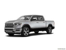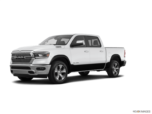



How to Replace Front Control Arms on a 2019-2021 Ram 1500 (Trim: Laramie Longhorn | Engine: V8 5.7L)
Step-by-step suspension guide with tools, parts, torque specs, safety tips, and alignment notes for 2019, 2020, 2021
How to Replace Front Control Arms on a 2019-2021 Ram 1500 (Trim: Laramie Longhorn | Engine: V8 5.7L)
Step-by-step suspension guide with tools, parts, torque specs, safety tips, and alignment notes for 2019, 2020, 2021


🔧 1500 - Front Control Arm Replacement
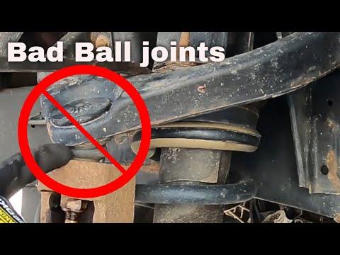
This repair replaces the front suspension control arms on your 1500. Control arms hold the wheel hub in position and allow the suspension to move smoothly; worn bushings or ball joints can cause clunks, wandering steering, uneven tire wear, or poor alignment.
Assumption: This covers front upper and lower control arms on the 2019 Ram 1500 DT body. Replace left/right sides in pairs when wear is similar.
Difficulty Level: Advanced | Estimated Time: 4-7 hours
⚠️ Safety & Precautions
- ⚠️ Suspension parts are heavy and spring-loaded; support the lower control arm before removing fasteners.
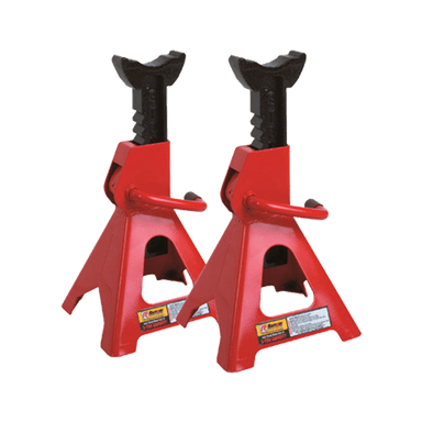
- ⚠️ Never work under your 1500 supported only by a jack. Use jack stands rated for the truck.
- ⚠️ Do not loosen the strut assembly center shaft nut. That nut holds spring pressure.
- ⚠️ Final tightening of control arm pivot bolts must be done at normal ride height to prevent bushing damage.
- ⚠️ If equipped with air suspension, disable air suspension/jack mode before lifting.
- ⚠️ A wheel alignment is required after replacing control arms.
- ⚠️ Battery disconnect is not normally required for this repair.
🔧 Required Tools
You'll need the following tools for this repair:
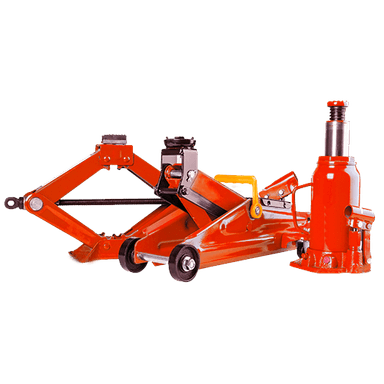
- Floor jack rated 3-ton minimum
- Jack stands rated 3-ton minimum
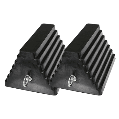
- Wheel chocks
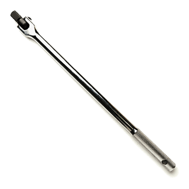
- 1/2-inch drive breaker bar
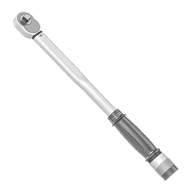
- 1/2-inch drive torque wrench rated to 250 ft-lbs
- 3/8-inch drive ratchet
- Metric socket set 10mm-24mm
- Metric wrench set 10mm-24mm
- 21mm socket
- 22mm socket
- 24mm socket
- 18mm wrench
- 21mm wrench
- 22mm wrench
- 24mm wrench
- Ball joint separator tool (specialty)
- Pry bar 24-inch
- Dead blow hammer
- Paint marker
- Needle nose pliers
- Penetrating oil
- Safety glasses
- Mechanic gloves
🔩 Required Parts
HowToo sells all the parts you need for this repair:
- Front upper control arm - Left: Qty: 1
- Front upper control arm - Right: Qty: 1
- Front lower control arm - Left: Qty: 1
- Front lower control arm - Right: Qty: 1
- Upper control arm mounting hardware kit - Qty: 1
- Lower control arm mounting hardware kit - Qty: 1
- Ball joint cotter pins - Qty: 4
- Front sway bar link nuts - Qty: 2
Note: If your replacement control arms come with new ball joints and bushings already installed, you do not need separate ball joints or bushings.
📋 Before You Begin
- Park your 1500 on flat, solid ground.
- Set the parking brake and place wheel chocks behind the rear wheels.
- If equipped with air suspension, turn on tire/jack mode using Uconnect: Apps > Settings > Suspension > Tire/Jack Mode.
- Loosen the front wheel lug nuts slightly before lifting the truck.
- Spray penetrating oil on the control arm bolts, ball joint nuts, and sway bar link nuts.
- Use a paint marker to mark the lower control arm cam bolt positions before loosening them. Cam bolts are alignment bolts with offset washers.
🔨 Step-by-Step Instructions
Follow these steps in order:
Step 1: Lift and Support the Front
- Use a 21mm socket and breaker bar to loosen the front lug nuts 1/2 turn.
- Use a floor jack rated 3-ton minimum to lift the front of your 1500 at the front crossmember.
- Place jack stands rated 3-ton minimum under the frame rails.
- Lower the truck gently onto the jack stands.
- Use a 21mm socket to remove the lug nuts and front wheels.
- Shake the truck gently to confirm stability.
Step 2: Support the Lower Control Arm
- Place the floor jack rated 3-ton minimum under the outer end of the lower control arm.
- Raise the jack just enough to support the arm. Do not lift the truck off the jack stands.
- This keeps the suspension from dropping suddenly when the ball joint is separated.
Step 3: Remove the Sway Bar Link from the Lower Control Arm
- Use an 18mm wrench and 18mm socket to remove the sway bar link nut at the lower control arm.
- Move the sway bar link out of the way.
- If the stud spins, hold the stud with the correct wrench flats while turning the nut with the socket.
Step 4: Separate the Upper Ball Joint
- Use needle nose pliers to remove the cotter pin from the upper ball joint nut.
- Use a 21mm socket or 22mm socket to loosen the upper ball joint nut a few turns, but do not remove it yet.
- Use a ball joint separator tool (specialty) to separate the upper ball joint from the steering knuckle.
- Once separated, remove the nut fully with the same socket.
- Guide the upper control arm upward and away from the knuckle.
- Installation torque: upper ball joint nut to steering knuckle: Torque to 54 Nm (40 ft-lbs), then tighten further only as needed to align the cotter pin hole.
Step 5: Remove the Upper Control Arm
- Use a 21mm socket and 21mm wrench to remove the two upper control arm frame bolts.
- Remove the upper control arm from the frame brackets.
- Compare the old and new upper control arms before installation.
- Install the new upper control arm into the frame brackets by hand.
- Install the bolts and nuts finger-tight only for now.
- Final ride-height torque: upper control arm frame bolts: Torque to 115 Nm (85 ft-lbs).
- Do not final-tighten bushings while hanging.
Step 6: Separate the Lower Ball Joint
- Keep the lower control arm supported with the floor jack rated 3-ton minimum.
- Use needle nose pliers to remove the cotter pin from the lower ball joint nut.
- Use a 24mm socket to loosen the lower ball joint nut a few turns.
- Use a ball joint separator tool (specialty) to separate the lower ball joint from the steering knuckle.
- Remove the lower ball joint nut fully with the 24mm socket.
- Support the steering knuckle so it does not hang by the brake hose or ABS wire.
- Installation torque: lower ball joint nut to steering knuckle: Torque to 95 Nm (70 ft-lbs), then tighten further only as needed to align the cotter pin hole.
Step 7: Mark and Remove the Lower Control Arm Bolts
- Use a paint marker to mark the position of each lower control arm cam washer against the frame.
- Use a 24mm socket and 24mm wrench to loosen the lower control arm mounting bolts.
- Remove the front and rear lower control arm bolts.
- Use a pry bar 24-inch if the lower control arm is tight in the frame pockets.
- Lower the arm slowly using the floor jack rated 3-ton minimum.
Step 8: Install the New Lower Control Arm
- Position the new lower control arm in the frame pockets.
- Use the floor jack rated 3-ton minimum to gently raise the arm into place.
- Install the lower control arm bolts and cam washers by hand.
- Line up the cam washers with the paint marks using the paint marker marks as a starting point.
- Do not final-tighten the lower control arm bolts yet.
- Final ride-height torque: lower control arm frame bolts: Torque to 285 Nm (210 ft-lbs).
Step 9: Connect the Lower Ball Joint
- Guide the lower ball joint stud into the steering knuckle.
- Install the lower ball joint nut by hand.
- Use a 24mm socket and torque wrench to tighten the nut.
- Torque to 95 Nm (70 ft-lbs), then tighten further only as needed to install the cotter pin.
- Use needle nose pliers to install a new cotter pin.
Step 10: Connect the Upper Ball Joint
- Pull the steering knuckle outward carefully and guide the upper ball joint stud into the knuckle.
- Install the upper ball joint nut by hand.
- Use a 21mm socket or 22mm socket and torque wrench to tighten the nut.
- Torque to 54 Nm (40 ft-lbs), then tighten further only as needed to install the cotter pin.
- Use needle nose pliers to install a new cotter pin.
Step 11: Reinstall the Sway Bar Link
- Position the sway bar link back into the lower control arm.
- Use an 18mm wrench and 18mm socket to tighten the sway bar link nut.
- Torque to 75 Nm (55 ft-lbs).
Step 12: Set Suspension to Ride Height
- Use the floor jack rated 3-ton minimum under the lower control arm to raise the suspension until the control arm sits near normal driving height.
- Normal ride height means the control arm angle looks like it does when the truck is sitting on its wheels.
- This step protects the rubber bushings from being twisted at rest.
Step 13: Final-Tighten Control Arm Pivot Bolts
- Use a 21mm socket, 21mm wrench, and torque wrench to tighten the upper control arm bolts.
- Torque to 115 Nm (85 ft-lbs).
- Use a 24mm socket, 24mm wrench, and torque wrench to tighten the lower control arm bolts.
- Torque to 285 Nm (210 ft-lbs).
- Ride-height tightening is very important.
Step 14: Reinstall Wheels and Lower the Truck
- Install the front wheels by hand.
- Use a 21mm socket to snug the lug nuts in a star pattern.
- Use the floor jack rated 3-ton minimum to lift the truck slightly and remove the jack stands.
- Lower the truck fully to the ground.
- Use a 21mm socket and torque wrench to tighten the lug nuts in a star pattern.
- Torque to 176 Nm (130 ft-lbs).
Step 15: Repeat on the Other Side
- Repeat the same procedure on the opposite side using the same tools.
- Replace control arms in pairs when possible to keep handling balanced.
✅ After Repair
- ✅ Start with a slow test drive in a quiet area.
- ✅ Listen for clunks, pops, or rubbing noises.
- ✅ Recheck lug nut torque after the first short drive: 176 Nm (130 ft-lbs).
- ✅ Schedule a professional 4-wheel alignment immediately. The cam bolts affect caster and camber.
- ✅ If equipped with air suspension, turn off tire/jack mode using Uconnect: Apps > Settings > Suspension > Tire/Jack Mode.
- ✅ If the steering wheel is off-center, avoid long driving until the alignment is completed.
💰 DIY vs Shop Cost
Shop Cost: $1,200-$2,200 (parts + labor + alignment)
DIY Cost: $450-$1,100 (parts only, depending on upper-only or full upper/lower replacement)
You Save: $600-$1,100 by doing it yourself!
Shop labor rates vary but typically run $100-$150/hour. This repair takes a shop approximately 4-6 hours plus alignment time.
🎯 Ready to get started?
HowToo makes it easy: same-day/2-day shipping on every part, plus all the tools and specialty tools you need! Check out the parts and tools sections below to add everything to your cart.