


How to Replace Front Control Arms on a 2014-2018 GMC Sierra 1500
Step-by-step upper and lower control arm guide with tools, parts, torque specs, and safety tips for 2014, 2015, 2016, 2017, 2018
How to Replace Front Control Arms on a 2014-2018 GMC Sierra 1500
Step-by-step upper and lower control arm guide with tools, parts, torque specs, and safety tips for 2014, 2015, 2016, 2017, 2018


🔧 Sierra 1500 - Control Arm Replacement
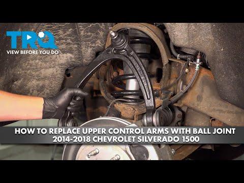
Replacing the control arms restores proper wheel alignment, suspension movement, and tire contact with the road. On your Sierra 1500, the front suspension uses upper and lower control arms; the procedure differs slightly depending on which arm you are replacing.
Assumption: This guide covers front upper and front lower control arms. Replace left/right sides in pairs when possible.
Difficulty Level: Advanced | Estimated Time: 3-5 hours per side
⚠️ Safety & Precautions
- ⚠️ The front coilover/strut supports vehicle weight. Do not loosen strut spring hardware unless using proper spring-service equipment.
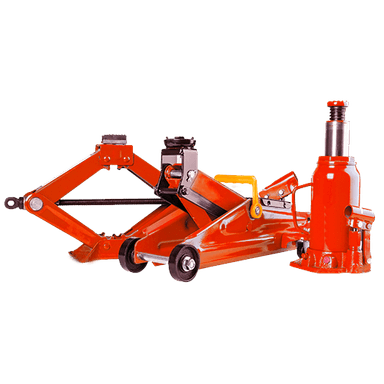
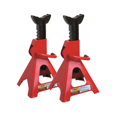
- ⚠️ Always support your Sierra 1500 with jack stands. Never work under a vehicle held only by a floor jack.
- ⚠️ The lower control arm is under suspension load. Keep the floor jack under it while separating ball joints.
- ⚠️ Use a torque wrench for final tightening. Suspension bolts that are too loose or too tight can be dangerous.
- ⚠️ Final control-arm pivot bolt tightening must be done at normal ride height to prevent bushing damage.
- ⚠️ A wheel alignment is required after control arm replacement.
🔧 Required Tools
You'll need the following tools for this repair:
- Floor jack (rated 3-ton minimum)
- Jack stands (rated 3-ton minimum)
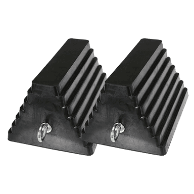
- Wheel chocks
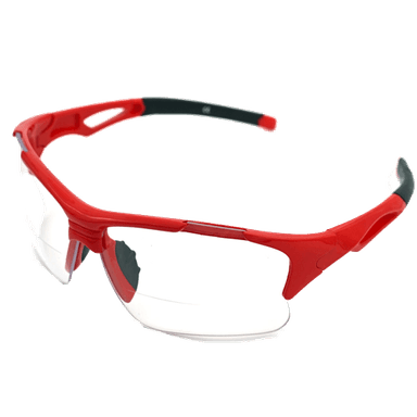
- Safety glasses
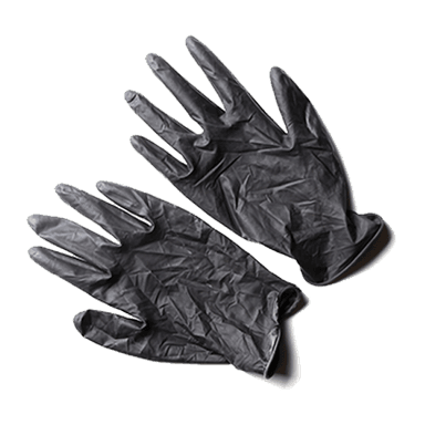
- Mechanic gloves
- Torque wrench (25-250 ft-lb range)
- Breaker bar 1/2-inch drive
- Ratchet 1/2-inch drive
- Ratchet 3/8-inch drive
- 15mm socket
- 18mm socket
- 21mm socket
- 22mm socket
- 24mm socket
- 15mm wrench
- 18mm wrench
- 21mm wrench
- 22mm wrench
- 24mm wrench
- 7mm socket
- 10mm socket
- Flathead screwdriver
- Needle-nose pliers
- Ball joint separator (specialty)
- Pickle fork ball joint tool (specialty)
- Hammer 3-lb
- Pry bar 24-inch
- Paint marker
- Tape measure
- Penetrating oil
🔩 Required Parts
HowToo sells all the parts you need for this repair:
- Front upper control arm - Left side Qty: 1
- Front upper control arm - Right side Qty: 1
- Front lower control arm - Left side Qty: 1
- Front lower control arm - Right side Qty: 1
- Front control arm bolt kit - Qty: 1
- Front ball joint nuts - Qty: 2-4
- Cotter pins - Qty: 2-4
- Wheel alignment - Qty: 1 service
📋 Before You Begin
- 🅿️ Park your Sierra 1500 on level ground and set the parking brake.
- 🧱 Place wheel chocks behind the rear wheels.
- 📏 Measure from the center of the front wheel hub to the lower edge of the fender with a tape measure. Write this down for ride-height tightening later.
- 🖊️ Use a paint marker to mark the position of the alignment cams on the lower control arm bolts. Alignment cams are eccentric washers that adjust wheel alignment.
- 💧 Spray penetrating oil on the control arm bolts, ball joint nuts, and sway bar link nuts before starting.
- 🔩 Loosen the front wheel lug nuts slightly before lifting the truck.
🔨 Step-by-Step Instructions
Follow these steps in order:
Step 1: Lift and Support the Front
- Use a floor jack under the front frame crossmember to raise your Sierra 1500.
- Place jack stands under the frame rails using the 3-ton jack stands.
- Lower the truck gently onto the jack stands.
- Use a floor jack to lightly support the lower control arm on the side you are working on.
Step 2: Remove the Front Wheel
- Use a 22mm socket and breaker bar to remove the lug nuts.
- Remove the wheel and set it flat under the frame as a backup safety cushion.
- Keep lug nuts together.
Step 3: Remove Brake Hose and ABS Wire Brackets
- Use a 10mm socket to remove the brake hose bracket from the upper control arm or frame bracket if equipped.
- Use a 7mm socket or flathead screwdriver to release ABS wire retainers from the control arm area.
- Do not pull on the ABS wire. Move it aside gently.
Step 4: Disconnect the Sway Bar Link if Replacing Lower Control Arm
- Use an 18mm socket and 18mm wrench to remove the sway bar link nut from the lower control arm.
- Push the sway bar link upward and away from the lower control arm.
- A sway bar link connects the suspension to the anti-roll bar, which helps reduce body lean while turning.
Step 5: Separate the Upper Ball Joint if Replacing Upper Control Arm
- Use needle-nose pliers to remove the cotter pin from the upper ball joint nut.
- Use an 18mm wrench or 18mm socket to loosen the upper ball joint nut a few turns, but do not remove it yet.
- Use a ball joint separator to separate the upper ball joint from the steering knuckle.
- A ball joint separator presses the tapered joint loose without hammering directly on the steering knuckle.
- Once loose, support the steering knuckle by hand and remove the nut fully with the 18mm wrench.
- Do not let the steering knuckle hang by the brake hose or ABS wire.
Step 6: Remove the Upper Control Arm
- Use a paint marker to mark the position of the upper control arm cam bolts if equipped.
- Use an 18mm socket and 18mm wrench to remove the two upper control arm mounting bolts and nuts.
- Slide the upper control arm out of the frame brackets.
- Compare the new upper control arm to the old one before installing.
Step 7: Install the New Upper Control Arm
- Position the new upper control arm in the frame brackets.
- Use an 18mm socket and 18mm wrench to install the mounting bolts and nuts finger-tight only.
- Insert the upper ball joint stud into the steering knuckle.
- Use an 18mm socket to tighten the upper ball joint nut.
- Torque upper ball joint nut to 50 Nm (37 ft-lbs), then tighten further as needed to align the cotter pin hole.
- Install a new cotter pin using needle-nose pliers.
- Do not fully torque the upper control arm pivot bolts until the suspension is at ride height.
Step 8: Separate the Lower Ball Joint if Replacing Lower Control Arm
- Keep the floor jack lightly supporting the lower control arm.
- Use needle-nose pliers to remove the cotter pin from the lower ball joint nut.
- Use a 24mm socket or 24mm wrench to loosen the lower ball joint nut a few turns, but do not remove it yet.
- Use a ball joint separator or pickle fork ball joint tool to separate the lower ball joint from the steering knuckle.
- A pickle fork is a wedge-shaped tool that separates joints, but it can damage old rubber boots.
- Once the joint pops loose, use a 24mm socket to remove the lower ball joint nut fully.
- Carefully lift the steering knuckle away and support it so the brake hose is not stretched.
Step 9: Remove the Strut Lower Bolts if Needed
- Use a 15mm socket and 15mm wrench to remove the lower strut mounting bolts from the lower control arm if they block removal.
- Do not loosen the center strut shaft nut.
- Support the strut by hand if it shifts slightly.
Step 10: Remove the Lower Control Arm
- Use a paint marker to mark the alignment cam positions on the front and rear lower control arm bolts.
- Use a 24mm socket and 24mm wrench to remove the front and rear lower control arm cam bolts and nuts.
- Use a pry bar 24-inch to gently work the lower control arm out of the frame pockets.
- Lower the floor jack slowly as the control arm comes free.
Step 11: Install the New Lower Control Arm
- Position the new lower control arm into the frame pockets.
- Use a pry bar 24-inch only as needed to align the bolt holes.
- Install the lower control arm cam bolts and nuts with the paint marks aligned as closely as possible.
- Use a 24mm socket and 24mm wrench to snug the bolts, but do not final torque yet.
- Install the lower ball joint stud into the steering knuckle.
- Use a 24mm socket to tighten the lower ball joint nut.
- Torque lower ball joint nut to 100 Nm (74 ft-lbs), then tighten further as needed to align the cotter pin hole.
- Install a new cotter pin using needle-nose pliers.
Step 12: Reinstall Strut Lower Bolts and Sway Bar Link
- Use a 15mm socket and 15mm wrench to reinstall the lower strut bolts.
- Torque lower strut bolts to 95 Nm (70 ft-lbs).
- Use an 18mm socket and 18mm wrench to reconnect the sway bar link to the lower control arm.
- Torque sway bar link nut to 65 Nm (48 ft-lbs).
Step 13: Reattach Brake Hose and ABS Wire Brackets
- Use a 10mm socket to reinstall the brake hose bracket.
- Torque small brake hose bracket bolt to 10 Nm (89 in-lbs).
- Use a 7mm socket or flathead screwdriver to secure ABS wire retainers in their original clips.
- Turn the steering left and right by hand to confirm the hose and wire do not stretch.
Step 14: Set Suspension to Ride Height
- Use the floor jack under the lower control arm to raise the suspension until your earlier hub-to-fender measurement is matched.
- This simulates the truck sitting on the ground.
- Final torque at ride height prevents bushing twist.
Step 15: Final Torque Control Arm Bolts
- Use an 18mm socket, 18mm wrench, and torque wrench to tighten the upper control arm pivot bolts.
- Torque upper control arm pivot bolts to 140 Nm (103 ft-lbs).
- Use a 24mm socket, 24mm wrench, and torque wrench to tighten the lower control arm cam bolts.
- Torque lower control arm cam bolts to 190 Nm (140 ft-lbs).
Step 16: Reinstall the Wheel
- Install the wheel by hand.
- Use a 22mm socket to snug the lug nuts in a star pattern.
- Lower your Sierra 1500 to the ground using the floor jack.
- Use a torque wrench and 22mm socket to tighten the lug nuts in a star pattern.
- Torque wheel lug nuts to 190 Nm (140 ft-lbs).
Step 17: Repeat on the Other Side if Replacing in Pairs
- Repeat the same steps on the other front side using the same tools.
- Replacing control arms in pairs helps keep handling even side-to-side.
✅ After Repair
- ✅ Bounce the front of your Sierra 1500 gently and listen for clunks.
- ✅ Check that brake hoses and ABS wires are clipped in and not stretched.
- ✅ Test drive slowly first. Listen for knocking, popping, or pulling.
- ✅ Get a professional wheel alignment immediately after replacing control arms.
- ✅ Recheck lug nut torque after 50-100 miles.
- ✅ If the steering wheel is off-center or the truck pulls, avoid highway driving until aligned.
💰 DIY vs Shop Cost
Shop Cost: $900-$1,800 per front pair, depending on upper/lower arms and alignment
DIY Cost: $250-$900 parts only, depending on arm quality and how many arms are replaced
You Save: $500-$900 by doing it yourself!
Shop labor rates vary but typically run $100-$150/hour. This repair takes a shop approximately 3-6 hours plus alignment time.
🎯 Ready to get started?
HowToo makes it easy: same-day/2-day shipping on every part, plus all the tools and specialty tools you need! Check out the parts and tools sections below to add everything to your cart.