

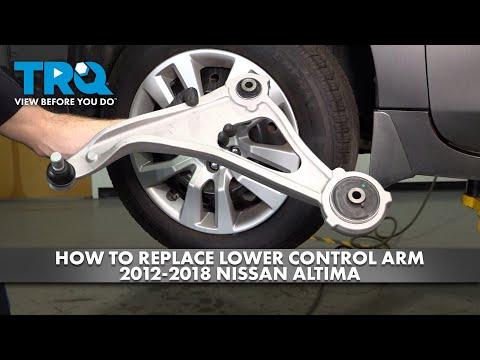


How to Replace Front Ball Joints on a 2019-2025 Nissan Altima
Step-by-step lower control arm replacement with tools, torque specs, and safety tips for 2019, 2020, 2021, 2022, 2023, 2024, 2025
How to Replace Front Ball Joints on a 2019-2025 Nissan Altima
Step-by-step lower control arm replacement with tools, torque specs, and safety tips for 2019, 2020, 2021, 2022, 2023, 2024, 2025


🔧 Altima - Front Lower Ball Joint Replacement
Replace the complete front lower control arm. On your Altima, Nissan supplies the lower control arm with the ball joint and bushings already installed, rather than servicing the joint separately. The correct assemblies are now showing in the parts section. parts.nissanusa.com)
This job involves heavily tightened suspension hardware. It’s manageable with patience, but it’s ambitious for a first repair.
Difficulty Level: Advanced | Estimated Time: 3-4 hours per side
Assumption: These instructions cover the front lower ball joints.
⚠️ Safety & Precautions
- ⚠️ Never work underneath an Altima supported only by a floor jack.
- ⚠️ Support the steering knuckle so it cannot pull on the brake hose or CV axle.
- ⚠️ Keep hands clear when separating the loaded control arm from the knuckle.
- ⚠️ Do not hammer the ball-joint stud, CV axle, aluminum knuckle, or brake rotor.
- ⚠️ Do not drive the car if the ball joint has visible separation or severe looseness.
- ⚠️ Battery disconnection is not required for this repair.
🔧 Required Tools
You'll need the following tools for this repair:
- 21mm six-point socket
- 18mm six-point socket
- 19mm six-point socket
- 18mm combination wrench
- 19mm combination wrench
- 1/2-inch drive ratchet
- 1/2-inch drive breaker bar
- 1/2-inch drive torque wrench rated to 150 ft-lbs
- 6-inch socket extension
- Ball-joint separator tool (specialty)
- 24-inch pry bar
- 16-ounce dead-blow hammer
- 3-ton floor jack
- 3-ton jack stands
- Rubber wheel chocks
- Steel wire brush
- Paint marker
- Mechanic’s wire
- Safety glasses
- Mechanic’s gloves
🔩 Required Parts
HowToo sells all the parts you need for this repair:
- Front lower control arm and ball-joint assembly - Qty: 1 per affected side
- New ball-joint retaining bolt and nut - Qty: 1 per side
- New control-arm mounting hardware - Qty: 1 set per side if specified with the replacement arm
- Penetrating oil - Qty: 1 can
Replacing both sides together is sensible when both joints or bushings show wear, but one sound arm doesn’t automatically need replacement. Suspension parts aren’t bananas. They don’t always spoil as a bunch.
📋 Before You Begin
- Park on level, solid pavement and apply the parking brake.
- Place rubber wheel chocks firmly behind both rear tires.
- Use the 21mm socket and breaker bar to loosen the front wheel nuts one-half turn.
- Spray penetrating oil on both inner control-arm fasteners and the ball-joint connection.
- Allow the penetrating oil to work for at least 15 minutes.
- Take pictures of the original arm and hardware orientation before removing anything.
- Have a wheel alignment scheduled after the repair.
🔨 Step-by-Step Instructions
Follow these steps in order:
Step 1: Lift and support the Altima
- Use the 3-ton floor jack at an approved front lifting point.
- Position both 3-ton jack stands beneath the reinforced front support points.
- Lower the car onto the stands and leave the floor jack lightly touching a support point.
- Push firmly against the body to confirm that the vehicle is stable.
- Use the 21mm socket and ratchet to remove the wheel.
Step 2: Inspect the new assembly
- Compare the new control arm with the original before disassembly.
- Confirm that its shape, mounting holes, bushings and ball-joint connection match.
- Check that the rubber ball-joint boot is seated and undamaged.
Step 3: Support the steering knuckle
- Loop mechanic’s wire around the steering knuckle and secure it to the strut spring.
- Leave enough movement for separation, but prevent the knuckle from hanging outward.
- Do not wrap the wire around the brake hose or ABS sensor cable.
Step 4: Mark the original mounting positions
- Use the paint marker to mark each inner control-arm fastener and its mounting location.
- These marks provide a reassembly reference but do not replace an alignment.
Step 5: Remove the ball-joint retaining fastener
- Use the steel wire brush to clean the exposed fastener and surrounding joint.
- Use the correctly fitting 18mm or 19mm six-point socket and matching wrench to remove the retaining bolt and nut.
- Confirm the socket fits fully before applying the breaker bar. Do not force an oversized socket.
- Discard hardware identified as one-time-use or supplied new with the control arm.
Step 6: Separate the ball joint from the knuckle
- Place the ball-joint separator between the control arm and steering knuckle.
- Operate the separator slowly until the joint releases.
- Use the pry bar only for gentle downward pressure on the control arm.
- Keep the separator and pry bar away from the rubber CV-axle boot.
- Steady pressure beats wild hammer swings.
Step 7: Remove the inner control-arm fasteners
- Support the outer end of the arm with the 3-ton floor jack.
- Use the 19mm socket, matching wrench and breaker bar to loosen the front mounting fastener.
- Use the 19mm socket, matching wrench and breaker bar to loosen the rear mounting fastener.
- Raise or lower the jack slightly if a bolt is trapped by bushing tension.
- Remove both fasteners while noting their direction and washer placement.
Step 8: Remove the control arm
- Lower the floor jack slowly until the arm is unloaded.
- Use the 24-inch pry bar carefully at the inner mounting pockets.
- Work the arm out of the subframe and remove it from the vehicle.
- Do not pry against brake pipes, steering components or the CV axle.
Step 9: Position the new control arm
- Slide the new arm into its inner mounting pockets.
- Install the front and rear fasteners by hand to avoid cross-threading.
- Use the 19mm socket and ratchet only to snug the fasteners.
- Do not apply final torque while the suspension hangs at full droop.
Step 10: Connect the ball joint
- Use the 3-ton floor jack beneath the outer control arm to align the ball joint with the knuckle.
- Guide the ball joint fully into position without damaging its rubber boot.
- Install the new retaining bolt and nut by hand.
- Use the correct 18mm or 19mm socket and torque wrench to tighten the ball-joint pinch fastener to 61-70 Nm (45-52 ft-lbs), following the specification supplied with the replacement hardware.
Step 11: Set the suspension at normal ride height
- Place the 3-ton floor jack under the outer end of the control arm.
- Raise the arm until the hub sits approximately at its normal loaded position.
- This prevents the bonded rubber bushings from being permanently twisted at rest.
Step 12: Tighten the inner mounting fasteners
- Use the 19mm socket and torque wrench while holding the suspension at ride height.
- Tighten each applicable inner control-arm mounting fastener to 165 Nm (122 ft-lbs).
- Verify that the arm remains seated squarely in both mounting pockets.
Step 13: Inspect the installation
- Use a flashlight to check that the ball-joint boot is not pinched or torn.
- Confirm that every removed nut and bolt is installed and torqued.
- Remove the mechanic’s wire supporting the steering knuckle.
- Check the brake hose and ABS sensor cable for stretching or contact.
Step 14: Reinstall the wheel
- Install the wheel and start all five lug nuts by hand.
- Use the 21mm socket and ratchet to snug them in a star pattern.
- Use the 3-ton floor jack to raise the car and remove the jack stands.
- Lower the Altima completely onto the ground.
- Use the 21mm socket and torque wrench to tighten the lug nuts in a star pattern to 113 Nm (83 ft-lbs).
✅ After Repair
- Turn the steering wheel fully left and right while listening for contact or binding.
- Press the brake pedal several times before moving the car.
- Drive slowly in a safe area and listen for clunks or popping sounds.
- Stop immediately if the steering feels loose, the wheel shifts, or a heavy clunk remains.
- Have a four-wheel alignment performed before regular driving.
- Recheck the wheel-lug torque after approximately 80-100 km.
💰 DIY vs Shop Cost
Shop Cost: Approximately ₹20,000-₹45,000 per side, depending on parts and local labor
DIY Cost: Approximately ₹9,000-₹20,000 per side for parts and consumables
You Save: Approximately ₹10,000-₹25,000 by doing it yourself!
Local Sonīpat labor and alignment charges vary. This repair generally takes a shop approximately 1.5-2.5 hours per side.
🎯 Ready to get started?
HowToo makes it easy: same-day/2-day shipping on every part, plus all the tools and specialty tools you need! Check out the parts and tools sections below to add everything to your cart.