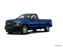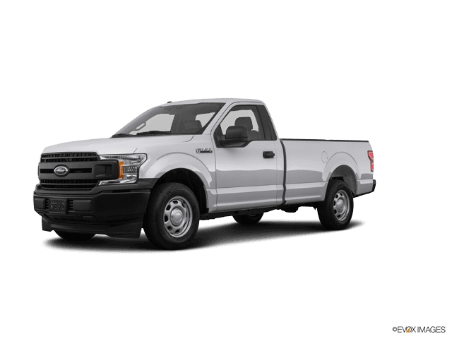

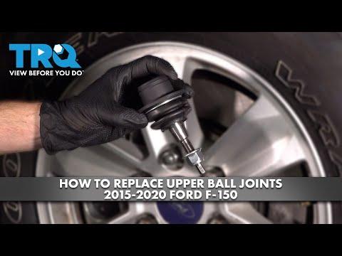


How to Replace Front Ball Joints on a 2015-2020 Ford F-150 (Trim: XL)
Step-by-step DIY guide with tools, parts, torque specs, safety tips, and alignment notes for 2015, 2016, 2017, 2018, 2019, 2020
How to Replace Front Ball Joints on a 2015-2020 Ford F-150 (Trim: XL)
Step-by-step DIY guide with tools, parts, torque specs, safety tips, and alignment notes for 2015, 2016, 2017, 2018, 2019, 2020


🔧 F-150 - Front Ball Joint Replacement
This repair replaces the front upper and lower ball joints on your F-150. Ball joints let the front suspension move while the wheels steer, and worn ones can cause clunks, wandering steering, tire wear, or unsafe looseness.
Difficulty Level: Advanced | Estimated Time: 4-6 hours per side
Assumption: This covers the RWD front suspension. Replace ball joints in pairs when wear is similar side-to-side.
⚠️ Safety & Precautions
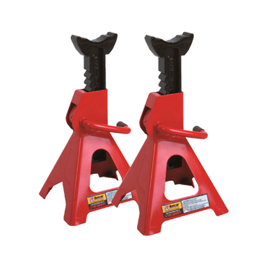
- ⚠️ Support your F-150 with jack stands under the frame. Never work under a truck held only by a jack.
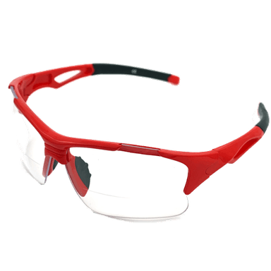
- ⚠️ Wear safety glasses. Ball joint tools and hammer impacts can release suddenly.
- ⚠️ Keep hands clear of the steering knuckle when separating ball joints.
- ⚠️ Do not let the brake caliper hang by the brake hose.
- ⚠️ A wheel alignment is required after replacing ball joints or disturbing control arm mounting bolts.
🔧 Required Tools
You'll need the following tools for this repair:
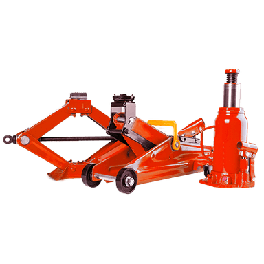
- Floor jack rated 3-ton minimum
- Jack stands rated 3-ton minimum
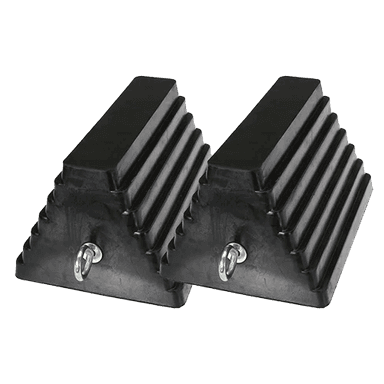
- Wheel chocks
- Safety glasses
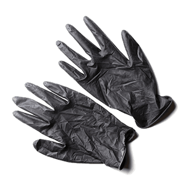
- Mechanic gloves
- 1/2-inch drive breaker bar
- 1/2-inch drive torque wrench 250 ft-lb capacity
- 3/8-inch drive ratchet
- 1/2-inch drive ratchet
- 10mm socket
- 13mm socket
- 15mm socket
- 18mm socket
- 21mm socket
- 24mm socket
- 15mm wrench
- 18mm wrench
- 21mm wrench
- 24mm wrench
- Ball joint press kit C-frame (specialty)
- Ball joint separator fork (specialty)
- Pickle fork adapter (specialty)
- Snap ring pliers
- Needle-nose pliers
- Flathead screwdriver
- Hammer 3-lb
- Pry bar 24-inch
- Paint marker
- Wire brush
- Bungee cord
- Penetrating oil
- Brake cleaner
- Grease gun
🔩 Required Parts
HowToo sells all the parts you need for this repair:
- Front upper ball joint - Qty: 1 per side
- Front lower ball joint - Qty: 1 per side
- Front ball joint castle nut kit - Qty: 1 per side
- Front ball joint cotter pins - Qty: 2 per side
- Chassis grease - Qty: 1 tube
📋 Before You Begin
- 🚗 Park on level ground, shift to Park, and set the parking brake.
- 🧱 Place wheel chocks behind both rear wheels.
- 🖊️ Use a paint marker to mark upper control arm cam bolt positions if you loosen those bolts.
- 🧰 Spray penetrating oil on the upper and lower ball joint nuts before starting.
- 📌 A ball joint press is a large C-shaped tool that pushes the ball joint in or out of the control arm.
- 📌 A castle nut is the slotted nut that uses a cotter pin to lock it in place.
🔨 Step-by-Step Instructions
Follow these steps in order:
Step 1: Loosen the Front Wheel Lug Nuts
- Use a 21mm socket and 1/2-inch drive breaker bar to loosen the front lug nuts one turn while the tire is still on the ground.
- Loose first, lift second.
Step 2: Lift and Support the Truck
- Use a floor jack rated 3-ton minimum under the front frame crossmember to raise the front of your F-150.
- Place jack stands rated 3-ton minimum under the front frame rails.
- Lower the truck onto the stands and gently shake the truck to confirm it is stable.
Step 3: Remove the Wheel
- Use a 21mm socket and 1/2-inch drive ratchet to remove the lug nuts.
- Remove the wheel and place it flat under the frame as an extra safety backup.
Step 4: Remove the Brake Caliper and Rotor
- Use a 13mm socket and 3/8-inch drive ratchet to remove the caliper slide bolts.
- Lift the caliper off the bracket.
- Use a bungee cord to hang the caliper from the frame.
- Use an 18mm socket and 1/2-inch drive breaker bar to remove the caliper bracket bolts.
- Slide the brake rotor off the hub.
Step 5: Move the ABS Wire and Brake Hose Brackets
- Use a 10mm socket and 3/8-inch drive ratchet to remove the ABS wire or brake hose brackets from the knuckle or control arm.
- Use a flathead screwdriver to gently release plastic clips.
- Move the wire and hose aside without pulling on them.
Step 6: Support the Lower Control Arm
- Place the floor jack rated 3-ton minimum under the lower control arm near the lower ball joint.
- Raise the jack until it just supports the arm.
- Do not lift the truck off the jack stand.
Step 7: Separate the Upper Ball Joint from the Knuckle
- Use needle-nose pliers to straighten and remove the upper cotter pin.
- Use a 21mm wrench or 21mm socket to loosen the upper castle nut.
- Leave the nut on a few threads to catch the knuckle when it pops loose.
- Use a ball joint separator fork and hammer 3-lb to separate the upper ball joint stud from the steering knuckle.
- Remove the upper castle nut fully after the taper breaks free.
Step 8: Separate the Lower Ball Joint from the Knuckle
- Use needle-nose pliers to straighten and remove the lower cotter pin.
- Use a 24mm socket or 24mm wrench to loosen the lower castle nut.
- Leave the nut on a few threads.
- Use the ball joint separator fork and hammer 3-lb to separate the lower ball joint stud from the steering knuckle.
- Remove the lower castle nut.
- Lift the steering knuckle and hub assembly off the lower ball joint.
- Set the knuckle aside carefully so the ABS wire and brake hose are not stretched.
Step 9: Remove the Upper Ball Joint
- If the upper ball joint has a snap ring, use snap ring pliers to remove it.
- Set up the ball joint press kit C-frame with the correct receiver cup under the upper control arm.
- Use a 1/2-inch drive breaker bar to turn the press screw and press the upper ball joint out.
- If your replacement part is a complete upper control arm, use an 18mm socket and 18mm wrench to remove the upper control arm bolts instead.
Step 10: Install the New Upper Ball Joint
- Use a wire brush to clean the upper control arm bore.
- Position the new upper ball joint straight in the bore.
- Use the ball joint press kit C-frame and 1/2-inch drive breaker bar to press the new joint fully into place.
- Use snap ring pliers to install the snap ring if supplied.
- If installing a complete upper control arm, snug the mounting bolts now with an 18mm socket and 18mm wrench. Final torque comes at ride height.
Step 11: Remove the Lower Ball Joint
- If the lower ball joint has a snap ring, use snap ring pliers to remove it.
- Place the ball joint press kit C-frame over the lower control arm with the receiver cup on the exit side.
- Use a 1/2-inch drive breaker bar to turn the press screw and push the lower ball joint out of the control arm.
- Keep the press straight.
Step 12: Install the New Lower Ball Joint
- Use a wire brush to clean the lower control arm bore.
- Start the new lower ball joint straight by hand.
- Use the ball joint press kit C-frame and 1/2-inch drive breaker bar to press the new joint fully into the control arm.
- Use snap ring pliers to install the snap ring if supplied.
- Check that the dust boot is seated and not pinched.
Step 13: Reinstall the Steering Knuckle
- Lift the steering knuckle and hub assembly onto the lower ball joint stud.
- Thread the lower castle nut on by hand.
- Guide the upper ball joint stud into the steering knuckle.
- Thread the upper castle nut on by hand.
Step 14: Torque the Ball Joint Nuts
- Use a 1/2-inch drive torque wrench 250 ft-lb capacity and 24mm socket to tighten the lower ball joint nut: Torque to 150 Nm (111 ft-lbs).
- Use a 1/2-inch drive torque wrench 250 ft-lb capacity and 21mm socket to tighten the upper ball joint nut: Torque to 85 Nm (63 ft-lbs).
- If the cotter pin hole does not line up, tighten the nut slightly more. Do not loosen it to line up the hole.
- Use needle-nose pliers to install new cotter pins through both castle nuts.
Step 15: Grease the New Ball Joints
- If the new ball joints have grease fittings, attach a grease gun to each fitting.
- Pump in chassis grease until the rubber boot just begins to swell.
- Stop before the boot looks stretched.
Step 16: Reinstall the Brake Rotor and Caliper
- Use brake cleaner to clean the rotor and hub face.
- Slide the rotor onto the hub.
- Use an 18mm socket and 1/2-inch drive torque wrench 250 ft-lb capacity to install the caliper bracket bolts: Torque to 184 Nm (136 ft-lbs).
- Set the caliper back over the bracket.
- Use a 13mm socket and 3/8-inch drive ratchet to install the caliper slide bolts: Torque to 35 Nm (26 ft-lbs).
Step 17: Reinstall ABS Wire and Brake Hose Brackets
- Use a 10mm socket and 3/8-inch drive ratchet to reinstall the ABS wire and brake hose brackets.
- Confirm the wire does not rub the tire, rotor, or suspension.
Step 18: Reinstall the Wheel
- Place the wheel on the hub.
- Start all lug nuts by hand.
- Use a 21mm socket and 1/2-inch drive ratchet to snug the lug nuts in a star pattern.
Step 19: Lower the Truck and Torque the Lug Nuts
- Use the floor jack rated 3-ton minimum to raise the truck slightly.
- Remove the jack stands rated 3-ton minimum.
- Lower your F-150 to the ground.
- Use a 1/2-inch drive torque wrench 250 ft-lb capacity and 21mm socket to torque the lug nuts in a star pattern: Torque to 204 Nm (150 ft-lbs).
Step 20: Final Torque at Ride Height
- If upper control arm mounting bolts were loosened, torque them with your F-150 sitting on its tires at normal ride height.
- Use an 18mm socket, 18mm wrench, and 1/2-inch drive torque wrench 250 ft-lb capacity.
- Upper control arm mounting bolts: Torque to 203 Nm (150 ft-lbs).
✅ After Repair
- ✅ Pump the brake pedal until it feels firm before moving the truck.
- ✅ Turn the steering wheel left and right while parked to check for binding or noises.
- ✅ Test drive slowly first, then recheck for clunks.
- ✅ Recheck lug nut torque after 25-50 miles: Torque to 204 Nm (150 ft-lbs).
- ✅ Schedule a front wheel alignment immediately.
💰 DIY vs Shop Cost
Shop Cost: $750-$1,400 per side including parts, labor, and alignment
DIY Cost: $120-$350 per side for parts only
You Save: $500-$1,000+ by doing it yourself!
Shop labor rates vary but typically run $100-$150/hour. This repair takes a shop approximately 3-5 hours per side.
🎯 Ready to get started?
HowToo makes it easy: same-day/2-day shipping on every part, plus all the tools and specialty tools you need! Check out the parts and tools sections below to add everything to your cart.