


How to Replace Front Ball Joints on a 2015-2020 Ford F-150 4WD (Trim: XL)
Step-by-step guide with required tools, parts, torque specs, and safety tips for 2015, 2016, 2017, 2018, 2019, 2020
How to Replace Front Ball Joints on a 2015-2020 Ford F-150 4WD (Trim: XL)
Step-by-step guide with required tools, parts, torque specs, and safety tips for 2015, 2016, 2017, 2018, 2019, 2020


🔧 F-150 - Front Ball Joint Replacement
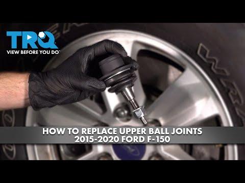
On your F-150, the front upper ball joint is built into the upper control arm, so the upper control arm is replaced as an assembly. The front lower ball joint is pressed into the steering knuckle and requires a ball joint press to remove and install it.
Difficulty Level: Advanced | Estimated Time: 3-5 hours per side
Assumption: This procedure covers front ball joints on your 4WD F-150.
⚠️ Safety & Precautions
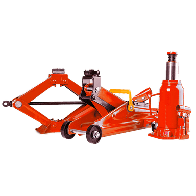
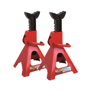
- ⚠️ Support your F-150 with jack stands only; never work under a truck held by a jack.
- ⚠️ The front suspension is heavy. Keep hands clear when separating the ball joint from the knuckle.
- ⚠️ Do not let the brake caliper hang by the brake hose. Support it with wire or a bungee cord.
- ⚠️ Avoid pulling on the front axle shaft or damaging the CV boot on your 4WD F-150.
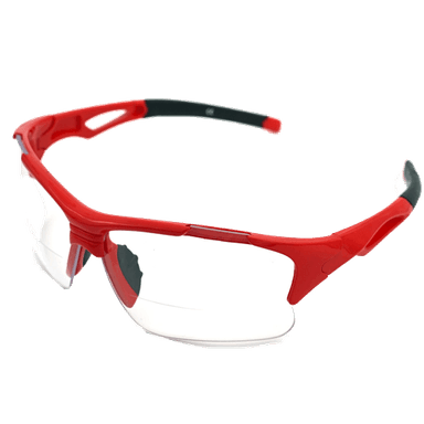
- ⚠️ A ball joint press is a clamp-style tool that pushes the ball joint in or out using force. Use safety glasses while pressing.
- ⚠️ An alignment is required after replacing upper control arms or disturbing suspension geometry.
- ⚠️ Battery disconnect is not required for this repair.
🔧 Required Tools
You'll need the following tools for this repair:
- Floor jack (rated 3-ton minimum)
- Jack stands (rated 3-ton minimum)
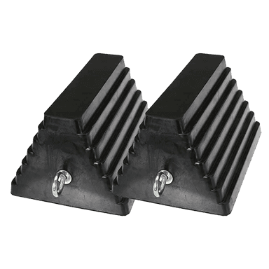
- Wheel chocks
- Safety glasses
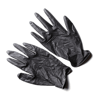
- Mechanic gloves
- 1/2-inch drive breaker bar
- 1/2-inch drive torque wrench (250 ft-lb range)
- 3/8-inch drive torque wrench (100 ft-lb range)
- 21mm socket
- 18mm socket
- 15mm socket
- 10mm socket
- 8mm socket
- 21mm wrench
- 18mm wrench
- 15mm wrench
- 8mm wrench
- Pry bar set
- Ball joint separator (specialty)
- Ball joint press kit (specialty)
- Snap ring pliers (specialty)
- Hammer
- Needle-nose pliers
- Flat-blade screwdriver
- Bungee cord
- Paint marker
- Wire brush
- Brake cleaner
🔩 Required Parts
HowToo sells all the parts you need for this repair:
- Front upper control arm with ball joint - Qty: 1 per side
- Front lower ball joint - Qty: 1 per side
- Front lower ball joint snap ring - Qty: 1 per side
- Front lower ball joint cotter pin - Qty: 1 per side
- Front upper ball joint nut - Qty: 1 per side
- Front lower ball joint nut - Qty: 1 per side
- Front axle nut - Qty: 1 per side
- Brake cleaner - Qty: 1 can
- Anti-seize compound - Qty: 1 small tube
📋 Before You Begin
- Park your F-150 on flat, solid ground.
- Set the parking brake and place wheel chocks behind the rear wheels.
- Loosen the front wheel lug nuts slightly before lifting the truck.
- Use a paint marker to mark the upper control arm bolt positions. This helps keep the alignment close enough to drive to the alignment shop.
- Plan to replace ball joints in pairs if both sides show wear. Suspension parts wear together.
🔨 Step-by-Step Instructions
Follow these steps in order:
Step 1: Lift and Support the Front of the Truck
- Use the 21mm socket and breaker bar to loosen the front lug nuts one turn while the tire is still on the ground.
- Use the floor jack under the front frame lift point to raise your F-150.
- Place jack stands under the frame rails, then slowly lower the truck onto them.
- Use the floor jack lightly under the lower control arm to support suspension weight.
- Remove the lug nuts with the 21mm socket, then remove the wheel.
Step 2: Remove Brake Hose and ABS Wire Brackets
- Use the 10mm socket to remove the brake hose bracket from the steering knuckle.
- Use the 8mm socket or 8mm wrench to remove ABS wire brackets from the knuckle or upper control arm area.
- Move the hose and wire aside gently.
- Do not stretch brake hoses.
Step 3: Remove the Brake Caliper and Rotor
- Use the 18mm socket to remove the brake caliper bracket bolts.
- Lift the caliper and bracket off the rotor as one assembly.
- Use a bungee cord to hang the caliper from the frame or coil spring area.
- Slide the brake rotor off by hand. If stuck, tap around the rotor hat gently with the hammer.
- During reassembly, tighten the front caliper bracket bolts to Torque to 184 Nm (136 ft-lbs).
Step 4: Remove the Front Axle Nut
- Use the 21mm socket or correct axle nut socket from your kit to remove the front axle nut.
- Push the axle shaft inward slightly by hand to make sure it is free in the hub.
- If it sticks, thread the nut on a few turns and tap the nut gently with the hammer.
- During reassembly, install a new axle nut and tighten to Torque to 40 Nm (30 ft-lbs), then tighten an additional 90 degrees.
Step 5: Separate the Outer Tie Rod from the Knuckle
- Use needle-nose pliers to remove the cotter pin from the outer tie rod nut.
- Use the 21mm socket or 21mm wrench to remove the tie rod nut.
- Use the ball joint separator to separate the tie rod from the steering knuckle.
- Do not hit the threaded stud directly with a hammer.
- During reassembly, tighten the outer tie rod nut to Torque to 103 Nm (76 ft-lbs), then install a new cotter pin if equipped.
Step 6: Separate the Upper Ball Joint
- Use the 18mm wrench or 18mm socket to loosen and remove the upper ball joint nut.
- Use the ball joint separator to separate the upper ball joint from the steering knuckle.
- Keep the floor jack lightly supporting the lower control arm.
- During reassembly, tighten the upper ball joint nut to Torque to 85 Nm (63 ft-lbs).
Step 7: Separate the Lower Ball Joint
- Use needle-nose pliers to remove the lower ball joint cotter pin.
- Use the 21mm socket or 21mm wrench to loosen the lower ball joint nut.
- Leave the nut threaded on a few turns for safety.
- Use the ball joint separator to separate the lower ball joint from the steering knuckle.
- Remove the lower ball joint nut fully once the joint pops loose.
- During reassembly, tighten the lower ball joint nut to Torque to 150 Nm (111 ft-lbs), then install a new cotter pin if equipped.
Step 8: Remove the Steering Knuckle
- Pull the steering knuckle outward while guiding the CV axle through the hub by hand.
- Use the pry bar only if needed, and do not pry on the CV boot.
- Set the knuckle on a sturdy work surface.
- Keep the axle supported.
Step 9: Press Out the Lower Ball Joint
- Use the wire brush and brake cleaner to clean dirt and rust from the lower ball joint area.
- Use snap ring pliers to remove the lower ball joint snap ring.
- Set up the ball joint press kit with the correct receiver cup under the ball joint.
- Use the ball joint press kit to press the old lower ball joint out of the steering knuckle.
- Keep the press straight. If it tilts, stop and realign it.
Step 10: Press In the New Lower Ball Joint
- Clean the ball joint bore with the wire brush and brake cleaner.
- Apply a very light coat of anti-seize compound to the outer shell of the new ball joint only.
- Use the ball joint press kit to press the new lower ball joint squarely into the steering knuckle.
- Press until the ball joint seats fully against the knuckle.
- Use snap ring pliers to install the new snap ring fully into its groove.
- Snap ring must seat completely.
Step 11: Replace the Upper Control Arm
- Use the paint marker to mark the position of the upper control arm bolts if you have not already done so.
- Use the 18mm socket and 18mm wrench to remove the upper control arm mounting bolts and nuts.
- Remove the upper control arm from your F-150.
- Install the new upper control arm into place by hand.
- Install the mounting bolts and nuts loosely using the 18mm socket and 18mm wrench.
- Do not final-tighten the upper control arm bolts until the suspension is at normal ride height.
- At ride height, tighten the upper control arm mounting nuts to Torque to 150 Nm (111 ft-lbs).
Step 12: Reinstall the Steering Knuckle
- Guide the CV axle through the hub by hand while placing the steering knuckle onto the lower ball joint.
- Install the lower ball joint nut by hand first to avoid cross-threading.
- Use the 21mm socket to tighten the lower ball joint nut to Torque to 150 Nm (111 ft-lbs).
- Install a new cotter pin with needle-nose pliers.
- Install the upper ball joint stud into the knuckle.
- Use the 18mm socket or 18mm wrench to tighten the upper ball joint nut to Torque to 85 Nm (63 ft-lbs).
Step 13: Reinstall Tie Rod, Axle Nut, Rotor, and Caliper
- Install the outer tie rod into the knuckle by hand.
- Use the 21mm socket to tighten the tie rod nut to Torque to 103 Nm (76 ft-lbs).
- Install a new cotter pin with needle-nose pliers if equipped.
- Install the new axle nut by hand.
- Use the 21mm socket and torque wrench to tighten the axle nut to Torque to 40 Nm (30 ft-lbs), then tighten an additional 90 degrees.
- Slide the rotor onto the hub by hand.
- Install the caliper and bracket assembly.
- Use the 18mm socket to tighten the caliper bracket bolts to Torque to 184 Nm (136 ft-lbs).
Step 14: Reattach Brake Hose and ABS Wire Brackets
- Use the 10mm socket to reinstall the brake hose bracket.
- Use the 8mm socket or 8mm wrench to reinstall ABS wire brackets.
- Make sure the ABS wire is not twisted, stretched, or touching the tire.
Step 15: Load the Suspension and Final-Tighten the Upper Control Arm
- Use the floor jack under the lower control arm to raise the suspension until the truck just begins to lift off the jack stand.
- This simulates normal ride height.
- Use the 18mm socket, 18mm wrench, and torque wrench to tighten the upper control arm mounting nuts to Torque to 150 Nm (111 ft-lbs).
- Tightening at ride height prevents bushing damage.
Step 16: Reinstall the Wheel
- Install the wheel by hand.
- Use the 21mm socket to snug the lug nuts in a star pattern.
- Lower your F-150 with the floor jack.
- Use the 21mm socket and torque wrench to tighten the lug nuts to Torque to 204 Nm (150 ft-lbs).
✅ After Repair
- ✅ Pump the brake pedal several times before moving the truck. This seats the brake caliper back into position.
- ✅ Turn the steering wheel lock-to-lock while parked and listen for rubbing, clunks, or wire contact.
- ✅ Test drive slowly first. Check for pulling, noise, or steering wheel off-center.
- ✅ Recheck lug nut torque after the first short drive: Torque to 204 Nm (150 ft-lbs).
- ✅ Get a professional wheel alignment as soon as possible after replacing the upper control arm or ball joints.
💰 DIY vs Shop Cost
Shop Cost: $700-$1,400 per side (parts + labor)
DIY Cost: $180-$450 per side (parts only)
You Save: $520-$950 per side by doing it yourself!
Shop labor rates vary but typically run $100-$150/hour. This repair takes a shop approximately 3-5 hours per side.
🎯 Ready to get started?
HowToo makes it easy: same-day/2-day shipping on every part, plus all the tools and specialty tools you need! Check out the parts and tools sections below to add everything to your cart.