

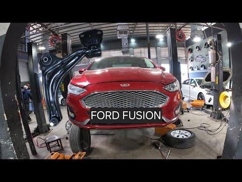


How to Replace Front Ball Joints on a 2013-2020 Ford Fusion (Engine: Inline 4 2.5L)
Step-by-step lower control arm guide with tools, parts, torque specs, and safety tips for 2013, 2014, 2015, 2016, 2017, 2018, 2019, 2020
How to Replace Front Ball Joints on a 2013-2020 Ford Fusion (Engine: Inline 4 2.5L)
Step-by-step lower control arm guide with tools, parts, torque specs, and safety tips for 2013, 2014, 2015, 2016, 2017, 2018, 2019, 2020


🔧 Fusion - Front Lower Ball Joint Replacement
On your Fusion, Ford services each front lower ball joint as part of the complete lower control arm. Replacing the control arm is safer and more reliable than pressing an aftermarket joint into the original arm, and it also renews both control-arm bushings.
Difficulty Level: Advanced | Estimated Time: 2-3 hours per side
Assumption: These instructions cover the front lower ball joints using complete replacement control arms.
⚠️ Safety & Precautions
- ⚠️ Never work beneath your Fusion while it is supported only by a jack.
- 🧤 Wear safety glasses and gloves; the joint can release suddenly when separated.
- 🚫 Do not strike the threaded ball-joint stud or pull on the brake hose.
- 🔩 Support the steering knuckle before separating the ball joint.
- 📐 A four-wheel alignment is required after replacing either control arm.
- 🔋 Battery disconnection is not required for this repair.
- 🛞 Replace control arms in pairs when possible because both sides usually wear similarly.
- 📏 Final control-arm fastener tightening must be performed at normal ride height to prevent bushing damage.
🔧 Required Tools
You'll need the following tools for this repair:
- 7mm socket
- 10mm socket
- 15mm socket
- 18mm socket
- 21mm socket
- 15mm combination wrench
- 18mm combination wrench
- 21mm combination wrench
- 1/2-inch drive ratchet
- 1/2-inch drive breaker bar
- 1/2-inch drive torque wrench rated 20-250 Nm
- 6-inch socket extension
- Front lower control-arm ball-joint separator (specialty)
- 12-inch pry bar
- 24-ounce dead-blow hammer
- Hydraulic floor jack rated 2-ton minimum
- Jack stands rated 2-ton minimum
- Wheel chocks
- Adjustable support stand rated 750-pound minimum
- Paint marker
- Wire brush
- Safety glasses
- Mechanic’s gloves
🔩 Required Parts
HowToo sells all the parts you need for this repair:
- Front lower control arm with ball joint, left - Qty: 1
- Front lower control arm with ball joint, right - Qty: 1
- Lower ball-joint prevailing-torque nuts - Qty: 2
- Lower control-arm mounting fastener kits - Qty: 2
- Penetrating lubricant - Qty: 1
Recommended: Replace the left and right control arms as a pair. Ford-design prevailing-torque nuts resist loosening and should not be reused.
📋 Before You Begin
- 🅿️ Park your Fusion on solid, level ground. Shift into Park and apply the parking brake.
- 🧱 Place wheel chocks securely behind both rear wheels.
- 🔍 Compare each new arm with the original side before removing anything. Left and right arms are different.
- 💧 Apply penetrating lubricant to the ball-joint nut and control-arm fasteners.
- 📱 Arrange a wheel alignment before driving any significant distance.
- 📖 Confirm the torque values supplied with the replacement arms if they differ from Ford service specifications.
🔨 Step-by-Step Instructions
Follow these steps in order:
Step 1: Loosen the Front Wheel Nuts
- Use a 21mm socket and breaker bar to loosen each front wheel nut about one-half turn.
- Do not remove the nuts while the vehicle is still on the ground.
Step 2: Raise and Support the Vehicle
- Use the floor jack beneath the approved front-center lifting point to raise your Fusion.
- Position the jack stands beneath the reinforced side support points.
- Lower the vehicle onto the stands, then gently push the body to confirm it is stable.
- Keep the floor jack nearby as a secondary support, but do not rely on it alone.
Step 3: Remove the Front Wheel
- Use the 21mm socket to remove the wheel nuts.
- Remove the wheel and place it flat outside your work area.
Step 4: Remove Obstructing Shields
- Inspect the lower splash shield around the control-arm fasteners.
- Use the 7mm socket and 10mm socket to remove only the shield fasteners blocking access.
- Keep the different fasteners organized for installation.
Step 5: Support the Steering Knuckle
- Place the adjustable support stand beneath the steering knuckle without contacting the brake rotor shield.
- Raise the stand just enough to carry the knuckle’s weight.
- Do not lift the vehicle from the jack stands.
Step 6: Disconnect the Ball Joint
- Use a wire brush to clean the exposed ball-joint threads.
- Use the appropriate 18mm or 21mm socket and matching wrench to remove the ball-joint nut, depending on the replacement fastener design.
- Install the ball-joint separator between the control arm and steering knuckle. A separator applies controlled pressure to release the tapered stud.
- Tighten the separator until the stud releases from the knuckle.
- Use the pry bar to move the arm downward and guide the stud out of the knuckle.
- Do not let the knuckle hang from the brake hose or wheel-speed-sensor wire.
- Leave the axle and hub nut untouched.
Step 7: Mark the Original Arm Position
- Use the paint marker to outline the rear bushing bracket against the subframe.
- Mark the installed direction of the front pivot bolt.
- These reference marks help place the replacement arm close to its original position.
Step 8: Remove the Lower Control Arm
- Use the 18mm or 21mm socket, matching wrench, breaker bar, and extension to loosen the rear bushing bracket fasteners.
- Use the 18mm or 21mm socket and matching wrench to remove the front pivot bolt.
- Support the arm by hand, then remove the rear bracket fasteners completely.
- Use the pry bar carefully to free the bushings from the subframe.
- Remove the complete control arm from your Fusion.
Step 9: Compare the New Control Arm
- Place the old and new arms side by side.
- Confirm the arm shape, bushing orientation, ball-joint stud, and bracket locations match.
- Make sure the protective boot is seated and has not been cut or twisted.
Step 10: Install the New Control Arm
- Guide the new arm into the subframe, rear bushing first.
- Use the ratchet and appropriate 18mm or 21mm socket to install the rear fasteners loosely.
- Align the front bushing and install the front pivot bolt in its original direction.
- Use the paint marks to position the rear bracket.
- Leave all bushing fasteners loose enough for the arm to rotate. Do not apply final torque yet.
Step 11: Connect the Ball Joint
- Use the pry bar to lower the control arm slightly while guiding the ball-joint stud into the steering knuckle.
- Install a new ball-joint nut by hand so the threads are not crossed.
- Use the specified socket and torque wrench to tighten the new nut to 80 Nm (59 ft-lbs).
- If the replacement control-arm manufacturer supplies a different torque specification, follow that specification.
Step 12: Load the Suspension at Ride Height
- Place the floor jack beneath the outer end of the control arm, close to the ball joint.
- Raise the jack slowly until the vehicle’s weight is nearly beginning to lift from that side’s jack stand.
- This places the suspension near normal ride height and prevents the rubber bushings from being locked in a twisted position.
- Keep the jack stand installed throughout this operation.
Step 13: Tighten the Control-Arm Fasteners
- Use the appropriate 18mm or 21mm socket, matching wrench, and torque wrench.
- Tighten the front control-arm pivot fastener to 200 Nm (148 ft-lbs).
- Tighten each rear control-arm bracket fastener to 175 Nm (129 ft-lbs).
- Use the exact specifications included with the replacement arm if its supplied fasteners or bracket design differ.
- Lower and remove the floor jack from beneath the arm.
Step 14: Reinstall the Splash Shield
- Use the 7mm socket and 10mm socket to reinstall the removed shield fasteners.
- Tighten the small fasteners only until snug; overtightening can crack the plastic shield.
Step 15: Reinstall the Wheel
- Install the wheel and start all five wheel nuts by hand.
- Use the 21mm socket and ratchet to seat them lightly in a star pattern.
- Repeat the complete procedure on the other side if replacing both arms.
Step 16: Lower the Vehicle and Torque the Wheels
- Use the floor jack to raise your Fusion slightly, remove the jack stands, and lower it to the ground.
- Use the 21mm socket and torque wrench to tighten the wheel nuts in a star pattern to 135 Nm (100 ft-lbs).
✅ After Repair
- 🔍 Turn the steering wheel fully left and right. Check that no hose, wire, or shield contacts a moving part.
- 🛞 Drive slowly in a safe area and listen for clunks or rubbing.
- 📐 Have a four-wheel alignment performed immediately. Control-arm replacement changes wheel alignment.
- 🔧 Recheck the wheel-nut torque after approximately 80-160 km.
- 🚨 Stop driving if the steering wheel is severely off-center, the vehicle pulls strongly, or any joint makes noise.
💰 DIY vs Shop Cost
Shop Cost: ₹30,000-₹55,000 (parts, labor, and alignment)
DIY Cost: ₹14,000-₹30,000 (parts and alignment)
You Save: ₹16,000-₹25,000 by doing it yourself!
Panipat labor and imported Fusion-part pricing vary. This repair takes a shop approximately 2-4 hours for both sides, plus alignment.
🎯 Ready to get started?
HowToo makes it easy: same-day/2-day shipping on every part, plus all the tools and specialty tools you need! Check out the parts and tools sections below to add everything to your cart.