

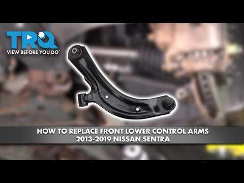


How to Replace Front Ball Joints on a 2013-2019 Nissan Sentra
Step-by-step lower control arm replacement with tools, torque specs, and safety tips for 2013, 2014, 2015, 2016, 2017, 2018, 2019
How to Replace Front Ball Joints on a 2013-2019 Nissan Sentra
Step-by-step lower control arm replacement with tools, torque specs, and safety tips for 2013, 2014, 2015, 2016, 2017, 2018, 2019


🔧 Sentra - Front Lower Ball Joint Replacement
On your Sentra, the front lower ball joint is supplied as part of the lower control arm, also called the transverse link. The safest manufacturer-style repair is to replace the complete control-arm assembly rather than press an aftermarket joint into the old arm.
Difficulty Level: Intermediate | Estimated Time: 2-3 hours per side
Assumption: These instructions cover one front lower control arm; repeat them on the opposite side if needed.
⚠️ Safety & Precautions
- ⚠️ Never work beneath your Sentra while it is supported only by a floor jack.
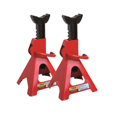
- 🛞 Support the vehicle with jack stands at the front body support points.
- 🧤 Wear safety glasses and mechanic’s gloves because rust and debris may fall during removal.
- 🔩 Do not loosen the axle nut; axle removal is unnecessary for this repair.
- 📐 Have a four-wheel alignment performed after replacing a control arm.
- 🔋 Battery disconnection is not required.
- 🚫 Do not drive if the ball-joint stud, nut, or control-arm mounting bolts cannot be fully tightened.
🔧 Required Tools
You'll need the following tools for this repair:
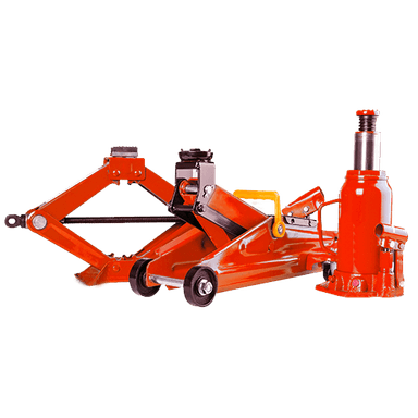
- Hydraulic floor jack rated 2-ton minimum
- Jack stands rated 2-ton minimum
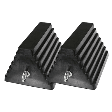
- Wheel chocks
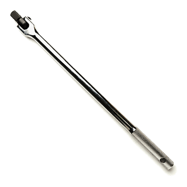
- 1/2-inch drive breaker bar
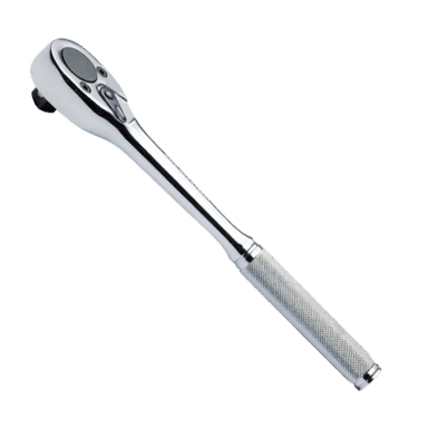
- 1/2-inch drive ratchet
- 3/8-inch drive ratchet
- 16mm combination wrench
- 18mm combination wrench
- 21mm combination wrench
- 16mm six-point socket
- 18mm six-point socket
- 21mm six-point socket
- 21mm deep wheel-nut socket
- 1/2-inch drive extension set
- Torque wrench rated 20-200 Nm
- Ball-joint separator (specialty)
- Medium pry bar
- 16-ounce ball-peen hammer
- Needle-nose pliers
- Wire brush
- Paint marker
- Penetrating oil aerosol
- Mechanic’s gloves
- Safety glasses
🔩 Required Parts
HowToo sells all the parts you need for this repair:
- Front lower control-arm assembly with ball joint - Qty: 1 per side
- Lower ball-joint self-locking nut - Qty: 1 per side
- Lower control-arm mounting hardware set - Qty: 1 per side
Replacing both sides is recommended when both original joints have similar mileage or looseness, but it is not mandatory when only one side is damaged.
📋 Before You Begin
- 🅿️ Park on firm, level ground. Shift the manual transmission into first gear and apply the parking brake.
- 🧱 Place wheel chocks securely behind both rear tires.
- 📦 Compare the new control arm with the removed-side location. The left and right arms are different.
- 🧼 Spray penetrating oil on the ball-joint nut and both control-arm mounting fasteners. Allow several minutes for it to soak.
- 📱 No infotainment service mode, scan-tool command, electronic parking-brake procedure, or battery registration is required.
🔨 Step-by-Step Instructions
Follow these steps in order:
Step 1: Loosen the Front Wheel Nuts
- Use a 21mm deep wheel-nut socket and 1/2-inch drive breaker bar to loosen each wheel nut approximately one-half turn.
- Do not remove the nuts while the tire is still supporting the vehicle.
Step 2: Raise and Support the Vehicle
- Use the hydraulic floor jack under the reinforced front-center lifting point to raise your Sentra.
- Position the jack stands beneath the reinforced front side support points.
- Lower the vehicle gently onto the stands, then lightly shake the body to confirm it is stable.
- Keep the jack nearby as backup support.
Step 3: Remove the Front Wheel
- Use the 21mm deep wheel-nut socket and 1/2-inch drive ratchet to remove the wheel nuts.
- Remove the wheel and place it flat away from the work area.
Step 4: Inspect and Mark the Mounting Points
- Use a wire brush to clean dirt and corrosion from the ball-joint stud and control-arm fasteners.
- Use a paint marker to mark each fastener’s installed direction and the control arm’s position.
- Check that the steering-knuckle hole is not elongated and that the subframe mounting points are not bent.
Step 5: Disconnect the Ball Joint
- Use needle-nose pliers to remove the cotter pin if the installed ball-joint nut uses one.
- Use a 21mm six-point socket with the 1/2-inch drive breaker bar to loosen the ball-joint nut.
- Leave the nut threaded on by several turns while separating the joint. This prevents the knuckle from dropping suddenly.
- Fit the ball-joint separator between the control arm and steering knuckle. A ball-joint separator is a tool that safely pushes the tapered stud out of the knuckle.
- Tighten the separator with the appropriate socket and ratchet until the taper releases.
- If needed, strike the side of the knuckle boss with the 16-ounce ball-peen hammer. Do not hit the threaded stud, brake rotor, or ABS sensor.
- Remove the loosened nut with the 21mm six-point socket.
Step 6: Remove the Control-Arm Mounting Fasteners
- Support the outer end of the arm with the hydraulic floor jack without lifting the vehicle off its stand.
- Use the 18mm six-point socket, 18mm combination wrench, and 1/2-inch drive breaker bar to loosen the front control-arm mounting bolt.
- Use the 21mm six-point socket, 21mm combination wrench, and 1/2-inch drive breaker bar to remove the rear mounting fastener.
- Fastener head sizes can differ when previous repairs used aftermarket hardware; always use the snug-fitting six-point socket listed for the installed fastener.
- Remove the front mounting bolt last while supporting the control arm.
Step 7: Remove the Old Control Arm
- Use the medium pry bar carefully between the control-arm bushing and subframe bracket.
- Pull the ball-joint stud clear of the steering knuckle, then work the arm out of its brackets.
- Do not pull outward forcefully on the steering knuckle because that can overextend the inner CV joint or brake hose.
Step 8: Compare and Position the New Control Arm
- Place the old and new arms side by side. Confirm that the bushings, ball-joint angle, mounting holes, and overall shape match.
- Guide the new arm into the subframe brackets by hand.
- Use the medium pry bar only for gentle alignment of the bushing sleeves.
- Install the front and rear mounting fasteners by hand. Do not fully tighten them yet.
Step 9: Connect the New Ball Joint
- Move the steering knuckle over the new ball-joint stud by hand.
- Use the medium pry bar gently if additional alignment is needed. Keep the pry bar away from the rubber dust boot.
- Thread the new self-locking nut onto the stud by hand to prevent cross-threading.
- Use the 21mm six-point socket and torque wrench to tighten the ball-joint nut to 72 Nm (53 ft-lbs).
- If the replacement joint uses a castellated nut and cotter pin, continue tightening only enough to align the next slot, then install the supplied new cotter pin using needle-nose pliers. Never loosen the nut to align the slot.
Step 10: Load the Suspension Bushings
- Place the hydraulic floor jack beneath the control arm near the ball joint.
- Raise the arm carefully until it reaches its normal approximate ride-height position. Keep the vehicle’s weight supported by the jack stand.
- This step prevents the rubber bushings from being twisted when the vehicle returns to the ground.
Step 11: Tighten the Control-Arm Fasteners
- Use the 18mm six-point socket, 18mm combination wrench, and torque wrench to tighten the front control-arm fastener to 93 Nm (69 ft-lbs).
- Use the 21mm six-point socket, 21mm combination wrench, and torque wrench to tighten the rear control-arm fastener to 121 Nm (89 ft-lbs).
- Lower and remove the hydraulic floor jack from beneath the arm.
- Inspect the ball-joint dust boot and confirm it is not pinched, cut, or twisted.
Step 12: Reinstall the Wheel
- Install the wheel and start all five wheel nuts by hand.
- Use the 21mm deep wheel-nut socket and 1/2-inch drive ratchet to snug the nuts in a star pattern.
- Use the hydraulic floor jack to raise the vehicle, remove the jack stands, and lower the tire to the ground.
- Use the 21mm deep wheel-nut socket and torque wrench to tighten the wheel nuts in a star pattern to 113 Nm (83 ft-lbs).
✅ After Repair
- 🔍 Confirm that every mounting fastener is tightened and the ball-joint dust boot remains properly seated.
- 🔄 Turn the steering wheel slowly from lock to lock while parked. Listen for binding, clunks, or scraping.
- 🚗 Take a short, low-speed road test. Stop immediately if the steering feels loose or the vehicle pulls sharply.
- 📐 Arrange a four-wheel alignment as soon as possible because control-arm replacement can change toe and camber.
- 🔩 Recheck the wheel-nut torque to 113 Nm (83 ft-lbs) after approximately 80-160 km.
💰 DIY vs Shop Cost
Shop Cost: ₹12,000-₹24,000 per side (parts + labor + alignment)
DIY Cost: ₹5,000-₹12,000 per side (parts + alignment)
You Save: ₹7,000-₹12,000 by doing it yourself!
Labor rates around Sonīpat vary. This repair takes a shop approximately 1.5-2.5 hours per side, plus alignment time.
🎯 Ready to get started?
HowToo makes it easy: same-day/2-day shipping on every part, plus all the tools and specialty tools you need! Check out the parts and tools sections below to add everything to your cart.