

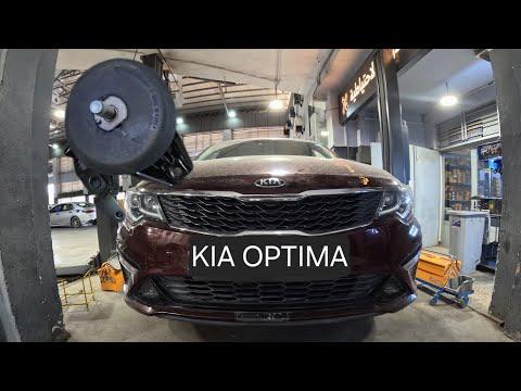



How to Replace Engine Mounts on a 2016-2020 Kia Optima 2.4L (Trim: LX | Engine: Inline 4 2.4L)
Step-by-step guide for all four mounts with tools, torque specs, and safety tips for 2016, 2017, 2018
How to Replace Engine Mounts on a 2016-2020 Kia Optima 2.4L (Trim: LX | Engine: Inline 4 2.4L)
Step-by-step guide for all four mounts with tools, torque specs, and safety tips for 2016, 2017, 2018


🔧 Optima - Engine Mount Replacement
Your Optima uses four main powertrain mounts: the passenger-side engine mount, driver-side transmission mount, front roll-stop mount, and rear roll-stop mount. This procedure replaces all four; replace only the failed mount if the others pass inspection.
Difficulty Level: Advanced | Estimated Time: 5-8 hours
Assumption: Procedures below cover the stock 2.4L gasoline engine and automatic transmission.
⚠️ Safety & Precautions
- ⚠️ Never remove a mount until the engine and transmission are securely supported.
- ⚠️ Use an engine support bar from above. A jack pressing directly against the aluminum oil pan can crack it.
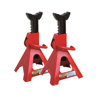
- ⚠️ Support the raised Optima with jack stands. Never work beneath a vehicle supported only by a jack.
- ⚠️ Allow the engine and exhaust system to cool completely.
- ⚠️ Disconnect the negative battery cable before removing the battery tray or transmission mount.
- ⚠️ Replace one mount at a time so the powertrain cannot shift excessively.
- ⚠️ Do not start the engine while any mount is disconnected.
- ⚠️ Mount fastener torque varies by mounting position and fastener diameter. Match every fastener to the torque listed in its installation step.
🔧 Required Tools
You'll need the following tools for this repair:
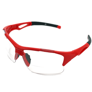
- Safety glasses
- Mechanic’s gloves
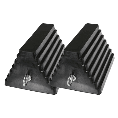
- Wheel chocks
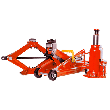
- Hydraulic floor jack rated 2-ton minimum
- Jack stands rated 2-ton minimum
- Engine support bar rated 1,000-pound minimum (specialty)
- Fender-cover set
- 3/8-inch-drive ratchet
- 1/2-inch-drive breaker bar
- 1/2-inch-drive torque wrench rated 20-150 ft-lbs
- 6-inch socket extension
- 12-inch socket extension
- 10mm socket
- 12mm socket
- 14mm socket
- 17mm socket
- 19mm socket
- 10mm combination wrench
- 12mm combination wrench
- 14mm combination wrench
- 17mm combination wrench
- 19mm combination wrench
- Phillips No. 2 screwdriver
- Trim-clip removal tool
- 8-inch alignment punch
- Paint marker
- LED work light
🔩 Required Parts
HowToo sells all the parts you need for this repair:
- Passenger-side engine mount - Qty: 1
- Driver-side transmission mount - Qty: 1
- Front roll-stop mount - Qty: 1
- Rear roll-stop mount - Qty: 1
- Engine-mount locking nuts and bolts - Qty: As required
- Transmission-mount locking nuts and bolts - Qty: As required
- Roll-stop mount locking nuts and bolts - Qty: As required
Replace self-locking nuts rather than reusing them.
📋 Before You Begin
- 📋 Park on firm, level ground. Shift to Park, apply the parking brake, and chock both rear wheels.
- 📋 Open the hood and protect both fenders with fender covers.
- 📋 Confirm each replacement mount matches the original mount’s bracket shape, stud locations, and electrical connections, if equipped.
- 📋 Take photographs before removing brackets, wire retainers, or ground cables.
- 📋 An engine support bar spans the strut towers and holds the powertrain from above with an adjustable chain.
- 📋 Record radio presets if desired. No battery registration or infotainment reset is required.
🔨 Step-by-Step Instructions
Follow these steps in order:
Step 1: Disconnect the Battery
- Use a 10mm wrench to loosen the negative battery-terminal nut.
- Remove the negative cable and position it where it cannot touch the terminal.
- Use a 10mm socket to remove the battery hold-down.
- Disconnect the positive terminal with the 10mm wrench, then lift out the battery while keeping it upright.
Step 2: Remove the Air-Cleaner and Battery Tray
- Use a 10mm socket and Phillips No. 2 screwdriver to loosen the intake clamp and remove the air-cleaner assembly.
- Release wiring retainers with the trim-clip removal tool. Do not pull directly on the wires.
- Use a 12mm socket and 6-inch extension to remove the battery-tray bolts, then lift out the tray.
- This exposes the driver-side transmission mount.
Step 3: Raise and Support the Vehicle
- Use the floor jack at the front-center lifting point to raise the Optima.
- Place the jack stands beneath the reinforced front side-support points and lower the vehicle onto them.
- Gently shake the vehicle to verify that it is stable before going underneath.
- Use a 10mm socket and trim-clip removal tool to remove the lower engine splash shield.
Step 4: Support the Powertrain
- Position the engine support bar across the protected strut-tower areas.
- Attach its chain to the factory engine lifting eye. Tighten the adjuster only until the chain becomes snug.
- Do not lift the vehicle or pull the engine upward with the support bar.
- Support the weight without changing engine height.
Step 5: Replace the Passenger-Side Engine Mount
- Mark the original mount position with the paint marker.
- Use a 17mm socket, 19mm socket, extensions, and breaker bar to loosen the mount-to-engine bracket fasteners and mount-to-body fasteners.
- Adjust the engine support bar slightly until the fasteners slide freely, then remove the mount.
- Position the new mount against the paint marks. Start every nut and bolt by hand to prevent crossed threads.
- Use the alignment punch only to align the holes; never force bolts through a misaligned mount.
- Use the torque wrench with the appropriate socket to tighten the M10 mount fasteners to 49-59 Nm (36-44 ft-lbs).
- Use the torque wrench with the appropriate socket to tighten the M12 mount fasteners to 88-108 Nm (65-80 ft-lbs).
Step 6: Replace the Driver-Side Transmission Mount
- Use the paint marker to mark the transmission mount’s installed position.
- Confirm the transmission remains supported by the engine support bar.
- Use a 17mm socket, 19mm socket, extensions, and breaker bar to remove the mount-to-transmission and mount-to-body fasteners.
- Adjust the engine support bar only enough to unload the mount, then remove it.
- Install the new mount and start all fasteners by hand.
- Use the torque wrench to tighten M10 fasteners to 49-59 Nm (36-44 ft-lbs).
- Use the torque wrench to tighten M12 fasteners to 88-108 Nm (65-80 ft-lbs).
Step 7: Replace the Front Roll-Stop Mount
- The roll-stop mount limits forward-and-back powertrain movement during acceleration and braking.
- Locate the front roll-stop mount below the radiator area using the LED work light.
- Use a 17mm socket, 19mm socket, extensions, and breaker bar to remove its through-bolt and bracket fasteners.
- Remove the old mount and compare its orientation with the replacement.
- Install the new mount with its molded arrow or orientation mark matching the original.
- Use the alignment punch to center the holes without prying against the rubber.
- Use the torque wrench to tighten M10 bracket fasteners to 49-59 Nm (36-44 ft-lbs).
- Use the torque wrench to tighten the M12 through-bolt to 107-127 Nm (79-94 ft-lbs).
Step 8: Replace the Rear Roll-Stop Mount
- Locate the rear roll-stop mount between the rear of the powertrain and front subframe using the LED work light.
- Use a 17mm socket, 19mm socket, 12-inch extension, and breaker bar to remove the through-bolt and bracket fasteners.
- If the mount cannot clear the exhaust or subframe without forcing it, stop. Subframe lowering requires powertrain support and alignment equipment and is not a beginner procedure.
- When clearance is available, remove the old mount and install the replacement in the same orientation.
- Use the alignment punch to align the holes and install every fastener by hand.
- Use the torque wrench to tighten M10 bracket fasteners to 49-59 Nm (36-44 ft-lbs).
- Use the torque wrench to tighten the M12 through-bolt to 107-127 Nm (79-94 ft-lbs).
Step 9: Remove the Engine Support
- Inspect all four mounts with the LED work light. Confirm that no hoses, wiring, or heat shields are trapped.
- Slowly loosen and remove the engine support bar.
- Watch each mount while unloading the support. The powertrain should settle only slightly.
Step 10: Reassemble the Engine Bay
- Install the battery tray using the 12mm socket. Tighten its fasteners securely without overtightening the thin tray.
- Reinstall all wiring retainers using the trim-clip removal tool.
- Install the air-cleaner assembly using the 10mm socket and Phillips No. 2 screwdriver.
- Install the battery and hold-down using the 10mm socket.
- Connect the positive cable first and negative cable last using the 10mm wrench.
Step 11: Reinstall the Splash Shield and Lower the Vehicle
- Install the splash shield using the 10mm socket and trim-clip removal tool.
- Use the floor jack to lift the vehicle slightly and remove the jack stands.
- Lower the Optima slowly and remove the rear wheel chocks.
✅ After Repair
- ✅ Start the engine with the transmission in Park. Listen for knocking, metal contact, or excessive vibration.
- ✅ Hold the brake firmly and shift slowly through Reverse, Neutral, and Drive. The engine should move slightly without clunking.
- ✅ If vibration is worse, shut the engine off and check for a twisted mount, trapped bracket, loose fastener, or exhaust contact.
- ✅ Take a short, low-speed test drive. Avoid hard acceleration until the installation has been checked.
- ✅ Reinspect all accessible mount fasteners and surrounding hoses after the test drive.
- ✅ The clock and saved radio settings may need to be restored after battery reconnection.
💰 DIY vs Shop Cost
Shop Cost: ₹65,000-₹120,000, approximately $775-$1,430 (parts + labor)
DIY Cost: ₹28,000-₹60,000, approximately $335-$715 (parts only)
You Save: ₹37,000-₹60,000, approximately $440-$715, by doing it yourself!
Local labor rates vary. This repair takes a shop approximately 4-6 hours, with additional labor if rear-mount access requires subframe movement.
🎯 Ready to get started?
HowToo makes it easy: same-day/2-day shipping on every part, plus all the tools and specialty tools you need! Check out the parts and tools sections below to add everything to your cart.