



How to Replace Engine Mounts on a 2016-2018 Chevrolet Malibu (Engine: Inline 4 1.5L)
Step-by-step guide for all three powertrain mounts, including tools, parts, and safety tips for 2016, 2017, 2018
How to Replace Engine Mounts on a 2016-2018 Chevrolet Malibu (Engine: Inline 4 1.5L)
Step-by-step guide for all three powertrain mounts, including tools, parts, and safety tips for 2016, 2017, 2018


🔧 Malibu - Engine Mount Replacement
Your Malibu uses three main powertrain mounts: the right-side engine mount, the left-side transmission mount, and the lower rear torque mount. This procedure replaces them one at a time so the engine and transmission remain safely supported.
Assumption: All three mounts are being replaced on a stock U.S.-market Malibu.
Difficulty Level: Advanced | Estimated Time: 5-7 hours
⚠️ Safety & Precautions
- Never work beneath an engine or transmission supported only by a floor jack.
- Use an engine support bar across the strut towers. This tool holds the powertrain from above while a mount is removed.
- Replace only one mount at a time. Removing multiple mounts can allow the powertrain to shift or fall.
- Do not place a jack directly against the aluminum oil pan or transmission case.
- Keep fingers clear while raising or lowering the powertrain to align a mount.
- Allow the turbocharger, exhaust, and engine to cool completely.
- Disconnect the negative battery cable before removing the battery tray or transmission-side mount.
- Use new GM-style prevailing-torque or torque-to-yield mount fasteners where specified. These fasteners are designed for one installation.
- Never use an impact wrench for final tightening.
🔧 Required Tools
You'll need the following tools for this repair:
- Engine support bar rated 1,000 pounds minimum (specialty)
- Engine lifting chain rated 1,000 pounds minimum
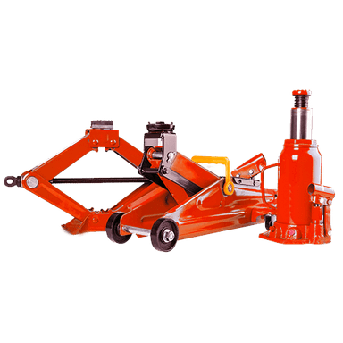
- Floor jack rated 2-ton minimum
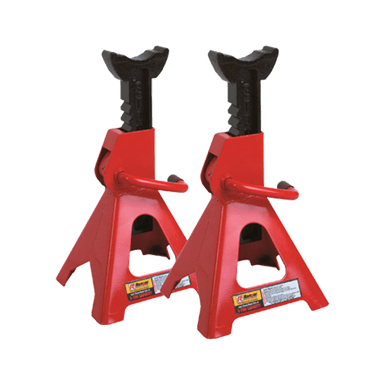
- Jack stands rated 2-ton minimum
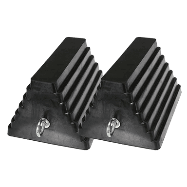
- Wheel chocks
- Wood block measuring approximately 25mm thick
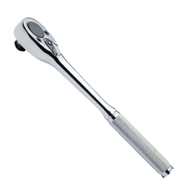
- 1/4-inch drive ratchet
- 3/8-inch drive ratchet
- 1/2-inch drive breaker bar
- 7mm socket
- 10mm socket
- 13mm socket
- 15mm socket
- 18mm socket
- 21mm socket
- 15mm deep socket
- 18mm deep socket
- 10mm combination wrench
- 15mm combination wrench
- 18mm combination wrench
- 3-inch socket extension
- 6-inch socket extension
- Torque wrench rated 10-80 Nm
- Torque wrench rated 40-200 Nm
- Torque-angle gauge (specialty)
- Flat trim-removal tool
- Paint marker
- Magnetic pickup tool
- Mechanic’s gloves
- Safety glasses
🔩 Required Parts
HowToo sells all the parts you need for this repair:
- Right-side engine mount - Qty: 1
- Left-side transmission mount - Qty: 1
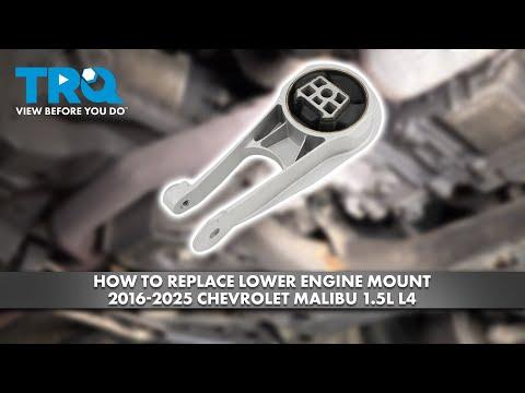
- Lower rear torque mount - Qty: 1
- Right-side engine mount fastener kit - Qty: 1
- Left-side transmission mount fastener kit - Qty: 1
- Lower rear torque mount fastener kit - Qty: 1
Important: Mount designs and service-fastener specifications can supersede during production. Use parts matched to your Malibu’s catalog record, and use the torque instructions supplied with any updated GM fastener kit.
📋 Before You Begin
- Park your Malibu on level, solid ground. Shift into Park, apply the parking brake, and switch the ignition off.
- Open the hood and remove all loose items from the engine compartment.
- Let the engine and exhaust cool completely.
- Chock both rear wheels before raising the front of the vehicle.
- Take pictures of hose, wiring, ground-strap, and battery-cable routing before disassembly.
- Use a paint marker to outline each mount’s original position before loosening it.
- Confirm that each replacement mount matches the removed mount before installation.
- No infotainment service mode, scan-tool command, battery registration, or programming is required.
🔨 Step-by-Step Instructions
Follow these steps in order:
Step 1: Disconnect the Battery
- Open the trunk and lift the luggage-compartment floor panel.
- Use a 10mm socket and 1/4-inch drive ratchet to loosen the negative battery terminal.
- Remove the negative cable and isolate it so it cannot spring back onto the terminal.
- Wait at least two minutes before working around starter or transmission wiring.
Step 2: Raise and Secure the Vehicle
- Use the floor jack at the front center lifting point, then position jack stands beneath the reinforced side support points.
- Lower your Malibu onto the jack stands and gently shake the body to verify stability.
- Keep the floor jack nearby, but do not rely on it as the primary support.
Step 3: Remove the Lower Splash Shield
- Use a 7mm socket, 10mm socket, and 1/4-inch drive ratchet to remove the lower shield screws.
- Use the flat trim-removal tool to release the plastic retainers without twisting them.
- Lower the shield and organize the fasteners by location.
- Push-pin centers release before their outer bodies.
Step 4: Install the Engine Support Bar
- Place the engine support bar across the approved strut-tower areas. Protect painted surfaces with the support bar’s padded feet.
- Attach the rated lifting chain to the factory engine lifting eye.
- Tighten the support bar only until the chain is snug. Do not lift the vehicle by the engine.
- Place the floor jack and wood block beneath a strong, flat powertrain support area as secondary support. Do not load the oil pan.
- Support the weight; do not raise the engine yet.
Step 5: Remove Obstructions Above the Right Mount
- Use a 7mm socket and 1/4-inch drive ratchet to loosen the air-inlet duct clamp.
- Disconnect the intake duct and move it aside without pulling on attached wiring.
- Use a 10mm socket and 3/8-inch drive ratchet to remove the air-cleaner housing fasteners if the housing blocks access.
- Release any wiring retainers with the flat trim-removal tool. Do not disconnect more connectors than necessary.
Step 6: Replace the Right-Side Engine Mount
- Mark the original mount position with the paint marker.
- Use the engine support bar to take the engine’s weight off the mount. Watch for slight mount relaxation, not visible engine lifting.
- Use the appropriate 15mm or 18mm socket, extension, and breaker bar to loosen the mount-to-body and mount-to-bracket fasteners.
- Remove the fasteners with the 3/8-inch drive ratchet, then lift out the mount. Raise or lower the support bar slightly if the mount is pinched.
- Inspect the engine bracket for cracks, bent metal, damaged threads, or fluid contamination.
- Position the new mount in the same orientation as the original. Install all new fasteners by hand before tightening any of them.
- Center the mount in the paint marks. Lower the supported engine only enough for the mount to sit naturally without side-loading.
- Use the torque wrench and torque-angle gauge to tighten the new fasteners to the specifications supplied with the GM-matched mount fastener kit. Do not reuse torque-to-yield bolts.
- If no verified fastener-kit specifications are supplied, stop before final tightening and obtain the current GM service-information values for the exact service fasteners installed.
Step 7: Remove the Battery and Battery Tray
- Use a 10mm socket and 1/4-inch drive ratchet to disconnect the positive battery terminal.
- Use a 13mm socket, extension, and 3/8-inch drive ratchet to remove the battery hold-down.
- Lift the battery straight upward while keeping it level. Batteries are heavy; use both hands.
- Use a 10mm or 13mm socket and 3/8-inch drive ratchet to remove the battery-tray fasteners.
- Release wiring retainers with the flat trim-removal tool, then remove the tray.
Step 8: Replace the Left-Side Transmission Mount
- Mark the transmission mount’s original position with the paint marker.
- Adjust the engine support bar until the transmission’s weight is removed from the mount.
- Use the appropriate 15mm or 18mm socket, extension, and breaker bar to loosen the mount-to-body and mount-to-transmission bracket fasteners.
- Remove the fasteners with the 3/8-inch drive ratchet. Move any wiring bracket aside without stretching its harness.
- Remove the mount. Adjust support height a few millimetres if the mount binds.
- Compare the new and old mounts, including locating tabs and bracket offset.
- Install the new mount and start every new fastener by hand. Do not pull the mount into place using the bolts.
- Align the paint marks and let the powertrain settle naturally against the mount.
- Use the torque wrench and torque-angle gauge to tighten the new fasteners to the specifications supplied with the GM-matched fastener kit.
- If verified specifications are not supplied, obtain the current GM service-information values before final tightening.
Step 9: Reinstall the Battery Tray and Battery
- Position the battery tray and engage every wiring retainer in its original location.
- Use a 10mm or 13mm socket and torque wrench to tighten the tray fasteners to the verified service specification for the installed fasteners.
- Lower the battery into the tray. Keep cables away from the battery base.
- Install the hold-down with a 13mm socket and torque wrench. Tighten it securely to the verified service specification without crushing the battery case.
- Connect the positive terminal with a 10mm socket. Leave the negative terminal disconnected until all work is complete.
Step 10: Replace the Lower Rear Torque Mount
- Work from beneath the vehicle only after confirming it is stable on both jack stands.
- Support the powertrain lightly with the engine support bar. The lower mount controls front-to-rear engine movement.
- Use an 18mm or 21mm socket and 1/2-inch drive breaker bar to loosen the lower mount through-bolts and bracket fasteners.
- Remove the fasteners with the 3/8-inch drive ratchet and appropriate socket.
- Remove the mount while noting its orientation. Use the engine support bar to shift the powertrain slightly if a bolt is loaded.
- Install the new mount in the same direction. Insert all new fasteners by hand.
- Allow the powertrain to settle into a neutral position before final tightening.
- Use the torque wrench and torque-angle gauge to tighten the new fasteners to the specifications supplied with the GM-matched fastener kit.
- If those specifications are unavailable, do not estimate them. Obtain the current GM service-information values before driving.
Step 11: Remove the Powertrain Supports
- Inspect all three mounts and confirm every fastener is installed and marked after final tightening.
- Slowly loosen the engine support bar while watching each mount for twisting or abnormal movement.
- Remove the lifting chain and engine support bar.
- Remove the floor jack and wood block from beneath the vehicle.
Step 12: Reassemble the Engine Compartment
- Reinstall the air-cleaner housing with the 10mm socket and 3/8-inch drive ratchet.
- Reconnect the intake duct and tighten its clamp with the 7mm socket.
- Reconnect all wiring retainers and confirm no harness is trapped beneath a mount or battery tray.
- Connect the negative battery terminal with the 10mm socket. Tighten it snugly without overtightening the terminal.
Step 13: Reinstall the Splash Shield and Lower the Vehicle
- Position the lower splash shield and install its retainers with the flat trim-removal tool.
- Install the screws with the 7mm and 10mm sockets. Tighten them gently because the shield retainers are plastic.
- Use the floor jack to lift your Malibu slightly, remove the jack stands, and lower the vehicle completely.
- Remove the rear wheel chocks.
✅ After Repair
- Before starting, inspect the engine compartment for tools, loose cables, and disconnected hoses.
- Start the engine with the transmission in Park. Watch the powertrain from a safe position and listen for knocking or metal contact.
- Hold the brake firmly and shift slowly through Reverse, Neutral, and Drive. A helper should watch for excessive engine movement while staying clear of the vehicle.
- Switch the engine off and inspect all mounts again for movement, misalignment, or loose hardware.
- Take a short, low-speed road test. Check for vibration at idle, clunks during acceleration, and contact between the exhaust and body.
- Battery disconnection may reset the clock, automatic-window express function, and some learned idle values. The idle may briefly fluctuate while the system relearns.
- If the check-engine light appears or vibration becomes worse, stop driving and recheck mount orientation, wiring, intake connections, and fastener tightening.
💰 DIY vs Shop Cost
Shop Cost: ₹45,000-₹85,000 including parts and labor
DIY Cost: ₹18,000-₹42,000 for parts and replacement fasteners
You Save: ₹20,000-₹45,000 by doing it yourself!
Labor rates around Sonīpat vary widely. This repair takes a properly equipped shop approximately 4-6 hours, with imported U.S.-market parts potentially increasing the total.
🎯 Ready to get started?
HowToo makes it easy: same-day/2-day shipping on every part, plus all the tools and specialty tools you need! Check out the parts and tools sections below to add everything to your cart.