


How to Replace Ball Joints on a 2018-2021 Ford Expedition
Step-by-step front control arm replacement guide with tools, parts, safety tips, and alignment notes for 2018, 2019, 2020, 2021
How to Replace Ball Joints on a 2018-2021 Ford Expedition
Step-by-step front control arm replacement guide with tools, parts, safety tips, and alignment notes for 2018, 2019, 2020, 2021


🔧 Ball Joints - Replacement
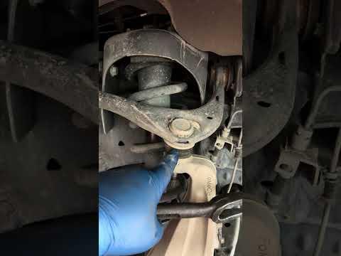
On your Expedition, the front upper ball joint is serviced with the upper control arm assembly, while the front lower ball joint is serviced with the lower control arm assembly. The ball joints are not a beginner-friendly press-out-only job on this platform; replacing the complete control arm assembly is the correct practical repair path.
Assumption: This guide covers front upper and front lower ball joint replacement by replacing the complete front control arm assemblies.
Difficulty Level: Advanced | Estimated Time: 4-7 hours for one side, 7-10 hours for both sides
⚠️ Safety & Precautions
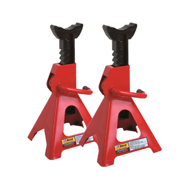
- ⚠️ Support your Expedition with jack stands only. Never work under a vehicle supported only by a floor jack.
- ⚠️ The front suspension is heavy. Keep hands clear when separating the ball joint from the steering knuckle.
- ⚠️ Do not hammer directly on aluminum steering knuckle mounting surfaces.
- ⚠️ Do not loosen or tighten final control arm pivot bolts with the suspension hanging. Final tightening must be done at normal ride height to protect the bushings.
- ⚠️ A wheel alignment is required after replacing control arms or ball joints.
- ⚠️ Battery disconnect is not required for this repair.
🔧 Required Tools
You'll need the following tools for this repair:
- Floor jack rated 3-ton minimum
- Jack stands rated 3-ton minimum
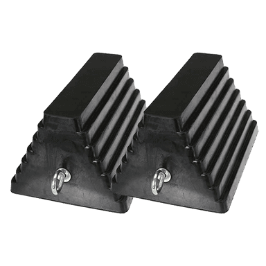
- Wheel chocks
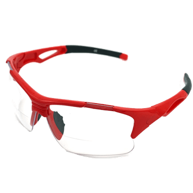
- Safety glasses
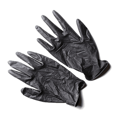
- Mechanic gloves
- 1/2-inch drive breaker bar
- 1/2-inch drive torque wrench rated to 250 ft-lbs
- 3/8-inch drive torque wrench rated to 100 ft-lbs
- 1/2-inch drive ratchet
- 3/8-inch drive ratchet
- Metric socket set 10mm-24mm
- Metric wrench set 10mm-24mm
- 21mm lug nut socket
- 18mm socket
- 21mm socket
- 24mm socket
- 18mm wrench
- 21mm wrench
- 24mm wrench
- Ball joint separator tool (specialty)
- Tie rod end separator tool (specialty)
- Pry bar 24-inch
- Dead blow hammer 3 lb
- Paint marker
- Needle nose pliers
- Trim clip removal tool
- Penetrating oil
- Shop rags
A ball joint separator is a fork or screw-style tool that safely pops the tapered ball joint stud loose from the steering knuckle.
🔩 Required Parts
HowToo sells all the parts you need for this repair:
- Front upper control arm assembly with ball joint - Left side Qty: 1 if replacing left
- Front upper control arm assembly with ball joint - Right side Qty: 1 if replacing right
- Front lower control arm assembly with ball joint - Left side Qty: 1 if replacing left
- Front lower control arm assembly with ball joint - Right side Qty: 1 if replacing right
- Front upper ball joint nut - Qty: 1 per side
- Front lower ball joint nut - Qty: 1 per side
- Front control arm mounting bolts and nuts - Qty: as needed
- Cotter pins - Qty: as needed
Replace in pairs: If one side is worn, it is best practice to replace the same control arm on both front sides for even handling and alignment.
📋 Before You Begin
- 🅿️ Park your Expedition on level ground and set the parking brake.
- 🧱 Place wheel chocks behind the rear wheels.
- 🖊️ Use a paint marker to mark the position of any alignment-related bolts before removal. This helps you drive carefully to the alignment shop.
- 🛞 Loosen the front wheel lug nuts slightly before lifting the vehicle.
- 🔎 Spray penetrating oil on the ball joint nuts and control arm bolts 10-15 minutes before starting.
- 📏 Plan for a professional wheel alignment immediately after the repair.
🔨 Step-by-Step Instructions
Follow these steps in order:
Step 1: Lift and Support the Front of the Vehicle
- Use the 21mm lug nut socket and 1/2-inch drive breaker bar to loosen the front wheel lug nuts one turn while the tire is still on the ground.
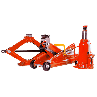
- Use the floor jack rated 3-ton minimum to lift the front of your Expedition at the approved front frame lift point.
- Place jack stands rated 3-ton minimum under the frame rails.
- Lower the vehicle gently onto the jack stands and lightly shake the vehicle to confirm it is stable.
- Never trust the jack alone.
Step 2: Remove the Front Wheel
- Use the 21mm lug nut socket and 1/2-inch drive ratchet to remove the loosened lug nuts.
- Remove the wheel and set it flat under the frame as an extra safety backup.
Step 3: Support the Lower Control Arm
- Place the floor jack rated 3-ton minimum under the outer end of the lower control arm.
- Raise the jack just enough to support the suspension. Do not lift the vehicle off the jack stand.
- This keeps the suspension from dropping suddenly when the ball joint is separated.
Step 4: Disconnect the Front Stabilizer Bar Link if Needed
- Use the correct size from the metric socket set 10mm-24mm and metric wrench set 10mm-24mm to remove the stabilizer bar link nut from the lower control arm if it blocks control arm movement.
- Move the link aside without stretching the brake hose or ABS wire.
- A stabilizer bar link connects the suspension to the sway bar to reduce body roll in turns.
Step 5: Separate the Outer Tie Rod if More Knuckle Movement Is Needed
- Use needle nose pliers to remove the cotter pin from the outer tie rod nut if equipped.
- Use the correct size from the metric socket set 10mm-24mm to remove the outer tie rod nut.
- Use the tie rod end separator tool (specialty) to separate the tie rod from the steering knuckle.
- Do not pull hard on the steering knuckle because the ABS wire and brake hose can be damaged.
Step 6: Remove the Upper Ball Joint Nut
- Use needle nose pliers to remove the cotter pin from the upper ball joint stud if equipped.
- Use the correct size from the metric socket set 10mm-24mm and metric wrench set 10mm-24mm to loosen and remove the upper ball joint nut.
- Leave the nut threaded on a few turns until the taper is broken loose. This helps keep the knuckle from jumping.
Step 7: Separate the Upper Ball Joint from the Steering Knuckle
- Use the ball joint separator tool (specialty) between the upper control arm ball joint and the steering knuckle.
- Tighten the separator until the taper pops loose.
- Remove the upper ball joint nut fully using the correct size from the metric socket set 10mm-24mm.
- Support the steering knuckle by hand and do not let it hang by the brake hose.
Step 8: Remove the Upper Control Arm Assembly
- Use the paint marker to mark the upper control arm mounting bolt positions.
- Use the correct size from the metric socket set 10mm-24mm and metric wrench set 10mm-24mm to remove the upper control arm mounting bolts and nuts.
- Remove the upper control arm assembly from the frame pocket.
- Install the new upper control arm assembly in the same orientation.
- Install the mounting bolts finger-tight only. Do not final-tighten yet.
Step 9: Install the New Upper Ball Joint into the Knuckle
- Guide the new upper ball joint stud into the steering knuckle by hand.
- Use the correct size from the metric socket set 10mm-24mm to install the new upper ball joint nut.
- Use the 3/8-inch drive torque wrench rated to 100 ft-lbs to tighten the upper ball joint nut to the specification supplied with the replacement control arm or OEM service data.
- Install a new cotter pin with needle nose pliers if the replacement joint uses a castle nut.
- Never reuse a bent cotter pin.
Step 10: Remove the Lower Ball Joint Nut
- Keep the floor jack rated 3-ton minimum supporting the lower control arm.
- Use needle nose pliers to remove the cotter pin from the lower ball joint stud if equipped.
- Use the correct size from the metric socket set 10mm-24mm and metric wrench set 10mm-24mm to loosen the lower ball joint nut.
- Leave the nut threaded on a few turns until the taper is separated.
Step 11: Separate the Lower Ball Joint from the Steering Knuckle
- Use the ball joint separator tool (specialty) to separate the lower ball joint stud from the steering knuckle.
- Once it pops loose, use the correct size from the metric socket set 10mm-24mm to remove the nut fully.
- Carefully lift the steering knuckle off the lower ball joint stud and support it so it does not pull the brake hose or ABS wire.
Step 12: Remove the Lower Control Arm Assembly
- Use the paint marker to mark the lower control arm mounting bolt positions.
- Use the correct size from the metric socket set 10mm-24mm, 1/2-inch drive breaker bar, and metric wrench set 10mm-24mm to loosen the lower control arm mounting bolts.
- Use the floor jack rated 3-ton minimum to slightly raise or lower the arm to remove bolt tension.
- Remove the lower control arm mounting bolts and remove the lower control arm assembly.
- The lower control arm is heavy, so keep one hand supporting it while removing the last bolt.
Step 13: Install the New Lower Control Arm Assembly
- Position the new lower control arm in the frame pockets.
- Use the pry bar 24-inch only as needed to align the bolt holes gently.
- Install the lower control arm mounting bolts by hand first to avoid cross-threading.
- Use the correct size from the metric socket set 10mm-24mm and metric wrench set 10mm-24mm to snug the bolts only. Do not final-tighten yet.
Step 14: Connect the Lower Ball Joint to the Steering Knuckle
- Guide the steering knuckle down over the new lower ball joint stud.
- Use the correct size from the metric socket set 10mm-24mm to install the new lower ball joint nut.
- Use the 1/2-inch drive torque wrench rated to 250 ft-lbs to tighten the lower ball joint nut to the specification supplied with the replacement control arm or OEM service data.
- Install a new cotter pin with needle nose pliers if the replacement joint uses a castle nut.
Step 15: Reconnect the Tie Rod and Stabilizer Link
- Use the correct size from the metric socket set 10mm-24mm to reinstall the outer tie rod nut if removed.
- Use the 3/8-inch drive torque wrench rated to 100 ft-lbs to tighten the tie rod nut to the specification supplied with the replacement part or OEM service data.
- Install a new cotter pin with needle nose pliers if used.
- Use the correct size from the metric socket set 10mm-24mm and metric wrench set 10mm-24mm to reinstall the stabilizer bar link if removed.
- Use the 3/8-inch drive torque wrench rated to 100 ft-lbs to tighten the stabilizer link fastener to the replacement part or OEM service specification.
Step 16: Set Suspension to Normal Ride Height Before Final Tightening
- Use the floor jack rated 3-ton minimum under the lower control arm to raise the suspension until the control arm sits near its normal driving angle.
- This is called loading the suspension. It prevents twisting and early failure of the rubber bushings.
- Use the 1/2-inch drive torque wrench rated to 250 ft-lbs with the correct socket from the metric socket set 10mm-24mm to final-tighten the upper and lower control arm mounting bolts to OEM specification.
- Torque must match OEM service data or the replacement control arm instructions for your Expedition.
Step 17: Reinstall the Wheel
- Use the 21mm lug nut socket and 1/2-inch drive ratchet to install the wheel lug nuts by hand.
- Snug the lug nuts in a star pattern. A star pattern means tightening across the wheel, not around in a circle.
- Use the floor jack rated 3-ton minimum to lift the vehicle slightly, remove the jack stands rated 3-ton minimum, and lower the vehicle to the ground.
- Use the 1/2-inch drive torque wrench rated to 250 ft-lbs and 21mm lug nut socket to tighten the lug nuts to Torque to 204 Nm (150 ft-lbs).
Step 18: Repeat on the Other Side if Replacing in Pairs
- Use the same tools and steps on the opposite front side.
- Keep left-side and right-side parts separate because control arms are side-specific.
✅ After Repair
- ✅ Turn the steering wheel slowly from lock to lock and listen for rubbing, popping, or binding.
- ✅ Check that the brake hose and ABS wire are routed correctly and not stretched.
- ✅ Road test at low speed first. Listen for clunks and confirm the steering feels normal.
- ✅ Recheck the wheel lug nut torque after the first short drive: Torque to 204 Nm (150 ft-lbs).
- ✅ Get a professional wheel alignment before normal driving. New control arms change camber and toe angles.
- ✅ Avoid highway speeds until the alignment is completed.
💰 DIY vs Shop Cost
Shop Cost: $900-$1,800 per side, $1,600-$3,200 both sides (parts + labor)
DIY Cost: $350-$900 per side, $700-$1,800 both sides (parts only)
You Save: $550-$1,400 by doing it yourself!
Shop labor rates vary but typically run $100-$150/hour. This repair takes a shop approximately 4-7 hours.
🎯 Ready to get started?
HowToo makes it easy: same-day/2-day shipping on every part, plus all the tools and specialty tools you need! Check out the parts and tools sections below to add everything to your cart.