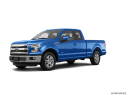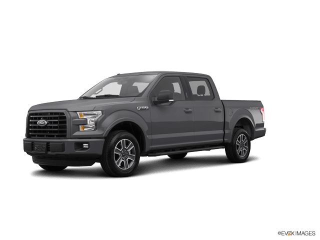

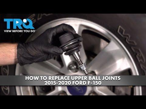
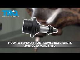


How to Replace All Front Ball Joints on a 2015-2020 Ford F-150 (Trim: Lariat)
Step-by-step upper and lower control arm replacement with tools, torque specs, and 2WD/4WD tips for 2015, 2016, 2017, 2018, 2019, 2020
How to Replace All Front Ball Joints on a 2015-2020 Ford F-150 (Trim: Lariat)
Step-by-step upper and lower control arm replacement with tools, torque specs, and 2WD/4WD tips for 2015, 2016, 2017, 2018, 2019, 2020


🔧 F-150 - All Front Ball Joint Replacement
On your F-150, the front ball joints are serviced most reliably by replacing both upper control-arm assemblies and both lower control-arm assemblies. This replaces all four ball joints without pressing joints into aluminum arms, and it also renews the control-arm bushings.
Difficulty Level: Advanced | Estimated Time: 6-10 hours
Assumption: This procedure covers both sides and includes separate 2WD and 4WD steps where required.
⚠️ Safety & Precautions
- ⚠️ Support your F-150 by the frame using properly rated jack stands. Never work beneath a vehicle supported only by a jack.
- ⚠️ The coil-over spring remains assembled. Do not remove the coil spring from the shock absorber.
- ⚠️ Support the steering knuckle so its weight cannot stretch the brake hose or wheel-speed sensor wire.
- ⚠️ Do not strike the aluminum steering knuckle directly with a steel hammer.
- ⚠️ Final-tighten control-arm pivot fasteners at normal ride height. Tightening them with the suspension hanging can damage the bushings.
- ⚠️ On 4WD models, do not pull the CV axle outward far enough to separate its inner joint.
- 🔋 Battery disconnection is not required.
- 🛞 A professional four-wheel alignment is required immediately afterward.
🔧 Required Tools
You'll need the following tools for this repair:
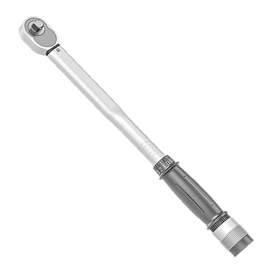
- 1/2-inch drive torque wrench rated 30-300 ft-lbs
- 3/8-inch drive torque wrench rated 10-100 ft-lbs
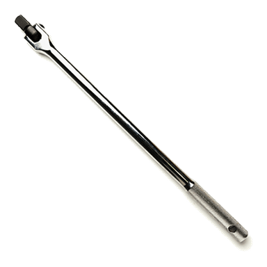
- 1/2-inch drive breaker bar
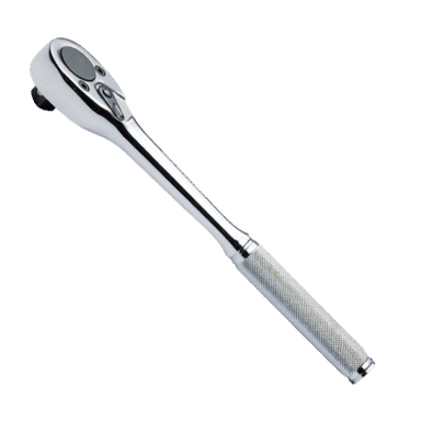
- 1/2-inch drive ratchet
- 3/8-inch drive ratchet
- 8mm socket
- 10mm socket
- 13mm socket
- 15mm socket
- 18mm socket
- 21mm socket
- 24mm socket
- 30mm 12-point axle-nut socket
- 21mm combination wrench
- 24mm combination wrench
- 6mm hex-bit socket
- Flat-blade screwdriver
- Needle-nose pliers
- Trim-clip removal tool
- Ball-joint separator (specialty)
- Two-jaw axle pusher (specialty)
- Paint marker
- Soft-face dead-blow hammer
- 24-inch pry bar
- Floor jack rated 3-ton minimum
- Four jack stands rated 3-ton minimum
- Wheel chocks
- Mechanic gloves
- Safety glasses
🔩 Required Parts
HowToo sells all the parts you need for this repair:
- Front upper control-arm assembly with ball joint - Qty: 2
- Front lower control-arm assembly with ball joint - Qty: 2
- Upper ball-joint nuts - Qty: 2
- Lower ball-joint nuts - Qty: 2
- Upper control-arm pivot fasteners - Qty: 4 sets
- Lower control-arm pivot fasteners - Qty: 4 sets
- Front axle nuts for 4WD models - Qty: 2
- Replacement cotter pins where supplied - Qty: 4
Replace in pairs: Install both upper arms and both lower arms. Use new prevailing-torque nuts and any one-time-use fasteners supplied with the arms.
📋 Before You Begin
- 🅿️ Park on firm, level ground. Set the parking brake and place the transmission in Park.
- 🧱 Chock both rear wheels with wheel chocks.
- 📱 No infotainment service mode or scan-tool command is required.
- 🖊️ Use a paint marker to outline the positions of the upper-arm alignment washers before removal. These marks preserve an approximate setting only; they do not replace an alignment.
- 📖 Compare every new arm with the original before installation. Left and right arms are different.
- 🔩 Confirm the instructions supplied with the replacement arms. If their fastener torque differs from the values below, follow the component manufacturer’s specification.
🔨 Step-by-Step Instructions
Follow these steps in order:
Step 1: Loosen the front fasteners
- Use a 21mm socket and 1/2-inch breaker bar to loosen each front wheel lug nut about one-half turn.
- On a 4WD model, remove the axle-nut retainer with needle-nose pliers. Use a 30mm 12-point axle-nut socket and breaker bar to loosen each front axle nut while the tires remain on the ground.
- Do not completely remove the lug nuts or axle nuts yet.
Step 2: Raise and support the truck
- Use the 3-ton floor jack under the front crossmember to raise your F-150.
- Place 3-ton jack stands under the frame rails behind the front wheels. Lower the frame securely onto the stands.
- Use the floor jack to apply light support beneath the lower control arm being serviced.
- Use a 21mm socket and ratchet to remove the lug nuts and wheel.
Step 3: Free the wiring and brake-hose brackets
- Use an 8mm or 10mm socket, as fitted, to remove the wheel-speed sensor wire and brake-hose bracket bolts from the steering knuckle and control arm.
- Use a trim-clip removal tool to release plastic harness retainers without pulling on the wires.
- Inspect the brake hose and sensor cable. Do not disconnect the hydraulic brake hose.
Step 4: Disconnect the stabilizer-bar link
- Use an 18mm socket to remove the stabilizer-link nut from the lower control arm.
- If the stud spins, hold it with a 6mm hex-bit socket while turning the nut with an 18mm combination wrench.
- Swing the link clear without forcing its rubber boots.
Step 5: Disconnect the tie-rod end
- Use needle-nose pliers to remove the cotter pin if one is fitted.
- Use a 21mm socket to remove the outer tie-rod nut.
- Use a ball-joint separator to release the tapered stud from the steering knuckle. A tapered stud is the cone-shaped pin that locks into the knuckle as its nut is tightened.
- Do not hammer the threaded end of the stud.
Step 6: Release the 4WD CV axle
- Skip this step on 2WD models.
- Use the 30mm 12-point axle-nut socket to remove the loosened axle nut.
- Thread the old axle nut backward until it is flush with the shaft end. Use a two-jaw axle pusher to press the CV axle inward through the hub.
- Remove the old nut and support the axle. Do not let it hang or pull outward on the inner joint.
- Never strike the axle threads.
Step 7: Separate the upper ball joint
- Use the floor jack to support the lower control arm and steering knuckle.
- Use an 18mm socket to loosen the upper ball-joint nut several turns, but leave it threaded on the stud.
- Use the ball-joint separator to release the stud from the knuckle.
- Remove the nut with the 18mm socket, then guide the upper arm away from the knuckle.
- Support the knuckle with a jack stand so the brake hose is not loaded.
Step 8: Remove the upper control arm
- Use a paint marker to trace the alignment washers and bolt positions on both frame brackets.
- Use a 21mm socket and 21mm combination wrench to remove the two upper-arm pivot bolts and nuts.
- Work the upper control-arm assembly out through the wheel opening without damaging the brake hose or wiring.
Step 9: Remove the lower shock fastener
- Keep the lower control arm supported with the floor jack.
- Use an 18mm socket and 18mm combination wrench to remove the shock absorber’s lower mounting bolt and nut.
- Do not loosen the shock’s center shaft nut. That nut retains the spring assembly.
Step 10: Separate the lower ball joint
- Use a 24mm socket to loosen the lower ball-joint nut several turns while leaving it on the stud.
- Use the ball-joint separator to release the tapered stud from the steering knuckle.
- Use the 24mm socket to remove the nut, then lift and support the knuckle clear of the lower arm.
- On 4WD models, guide the CV axle splines fully out of the hub while supporting both the axle and knuckle.
Step 11: Remove the lower control arm
- Use a 24mm socket, 24mm combination wrench, and breaker bar to loosen the front and rear lower-arm pivot fasteners.
- Use the floor jack to control the arm while removing both pivot bolts.
- Lower the jack slowly and remove the complete lower control-arm assembly.
- Use a soft-face dead-blow hammer and 24-inch pry bar only if the bushings are lightly stuck in the brackets.
Step 12: Install the new lower control arm
- Position the correct new lower arm in the frame brackets. Use the floor jack to align the bushings without cross-threading the bolts.
- Install the new pivot bolts and nuts using the 24mm socket and wrench. Leave them snug but not fully tightened.
- Guide the lower ball-joint stud into the steering knuckle.
- Install the new nut and use a 24mm socket with the torque wrench to torque the lower ball-joint nut to 150 Nm (111 ft-lbs).
- On 4WD models, guide the axle splines through the hub before fully seating the ball joint.
Step 13: Reconnect the shock and stabilizer link
- Use the floor jack to align the shock’s lower mount with the new control arm.
- Install the lower shock bolt and nut. Use an 18mm socket and torque wrench to torque to 90 Nm (66 ft-lbs).
- Install the stabilizer-link nut. Use an 18mm socket and torque wrench to torque to 48 Nm (35 ft-lbs).
- Hold the stud with the 6mm hex-bit socket if it turns.
Step 14: Install the new upper control arm
- Position the correct upper arm in the frame brackets with its ball-joint stud facing down.
- Install the new pivot fasteners using the 21mm socket and wrench. Align the washers with the paint marks and leave the fasteners snug.
- Insert the upper ball-joint stud into the steering knuckle.
- Use an 18mm socket and torque wrench to torque the upper ball-joint nut to 63 Nm (46 ft-lbs).
Step 15: Reconnect the tie rod and brackets
- Insert the tie-rod stud into the steering knuckle.
- Use a 21mm socket and torque wrench to torque the tie-rod nut to 115 Nm (85 ft-lbs).
- If a castellated nut is fitted, tighten only enough farther to align the next cotter-pin slot. Install a new cotter pin using needle-nose pliers.
- Use the 8mm or 10mm socket to reinstall the brake-hose and wheel-speed sensor brackets. Tighten the small bracket bolts securely by hand; do not overtighten them.
- Verify that the hose and sensor cable cannot touch the tire, axle, or suspension through steering travel.
Step 16: Install the 4WD axle nut
- Skip this step on 2WD models.
- Install a new axle nut by hand. Never reuse the removed prevailing-torque axle nut.
- Use the 30mm 12-point axle-nut socket and torque wrench to torque the new axle nut to 40 Nm (30 ft-lbs), then mark the nut and hub with the paint marker.
- Use the breaker bar to rotate the nut an additional 90 degrees.
- Install the retainer with needle-nose pliers if supplied.
Step 17: Repeat on the opposite side
- Use the same listed tools and repeat Steps 3-16 on the other front corner.
- Compare left and right hose routing before installing the wheels.
Step 18: Tighten the pivot bolts at ride height
- Use the floor jack beneath each lower arm to raise the suspension until the frame just begins lifting from its jack stand. This approximates normal ride height.
- Keep clear of pinch points and leave the jack stand in place as a safety backup.
- Use the 21mm socket, wrench, and torque wrench to torque each upper control-arm pivot nut to 165 Nm (122 ft-lbs).
- Use the 24mm socket, wrench, and high-range torque wrench to torque each lower control-arm pivot nut to 350 Nm (258 ft-lbs).
- Repeat this ride-height tightening process on the opposite side.
Step 19: Reinstall the wheels
- Use the 21mm socket to install the wheels and hand-tighten the lug nuts in a star pattern.
- Use the floor jack to remove the jack stands, then lower your F-150 until the tires touch the ground.
- Use the 21mm socket and torque wrench to tighten the lug nuts in a star pattern to 204 Nm (150 ft-lbs).
✅ After Repair
- 🔍 Turn the steering slowly from lock to lock. Confirm that no hose, wire, or boot stretches or rubs.
- 🛑 Pump the brake pedal several times before moving the truck, even though the brake hydraulic system was not opened.
- 🧪 Drive slowly in a safe area. Listen for clunks and verify that steering returns normally.
- 📐 Obtain a professional four-wheel alignment before normal driving. Replacing control arms changes camber, caster, and toe.
- 🔧 After 50-100 miles, visually inspect all fasteners, boots, wiring retainers, and axle-nut retainers. Do not loosen torque-to-yield fasteners to “check” them.
- ⚠️ Stop driving immediately if the steering binds, the wheel sits visibly crooked, or the ABS warning lamp appears.
💰 DIY vs Shop Cost
Shop Cost: $1,800-$3,200 (parts + labor)
DIY Cost: $650-$1,300 (parts only)
You Save: $1,150-$1,900 by doing it yourself!
Shop labor rates vary but typically run $100-$150/hour. This repair takes a shop approximately 5-8 hours, plus alignment.
🎯 Ready to get started?
HowToo makes it easy: same-day/2-day shipping on every part, plus all the tools and specialty tools you need! Check out the parts and tools sections below to add everything to your cart.