


2015 Ford Fusion Hybrid Charging System Repair: Fix “Alternator” Issues (DC/DC Converter)
Step-by-step diagnosis and DC/DC converter replacement with tools, parts list, safety tips, and charging voltage checks
2015 Ford Fusion Hybrid Charging System Repair: Fix “Alternator” Issues (DC/DC Converter)
Step-by-step diagnosis and DC/DC converter replacement with tools, parts list, safety tips, and charging voltage checks
🔧 Fusion - Alternator Replacement (Hybrid Charging System)
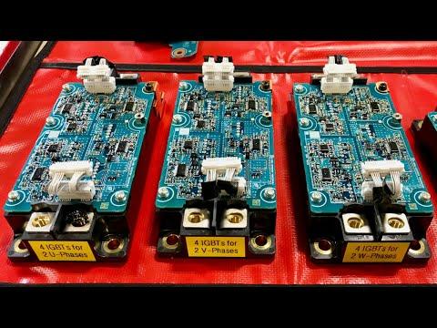
Your Fusion Hybrid does not use a traditional belt-driven alternator. The 12V system is charged by a DC/DC converter (it converts high-voltage battery power to ~14V to charge the 12V battery) and the engine is started by the hybrid drive system.
Assumption: You’re trying to fix a “battery not charging / low voltage” issue and were told “alternator.”
Difficulty Level: Advanced | Estimated Time: 2-4 hours
⚠️ Safety & Precautions
- ⚠️ High-voltage hybrid system can cause severe injury or death if handled incorrectly.
- ⚠️ Do not touch orange high-voltage cables or connectors.
- ⚠️ Disable high voltage using the proper service disconnect before any charging-system work (the service disconnect is a safety plug that isolates the high-voltage battery).
- ⚠️ Disconnect the 12V battery negative cable before unplugging modules/connectors.
- ⚠️ Wait time after HV shutdown may be required so capacitors can discharge.
- ⚠️ If you’re not trained on HV safety, have a shop perform this repair.
🔧 Required Tools
You'll need the following tools for this repair:
- Safety glasses
- Mechanic gloves
- Class 0 high-voltage insulating gloves (1000V rated) (specialty)
- Digital multimeter (CAT III rated)
- OBD2 scan tool with hybrid-capable data (specialty)
- 10mm socket
- 8mm socket
- 13mm socket
- 1/4" ratchet
- 3/8" ratchet
- 6" extension
- Trim clip removal tool
- Flat blade screwdriver
- Torque wrench (10–80 Nm range)
- Floor jack (rated 3-ton minimum)
- Jack stands (rated 3-ton minimum)
- Wheel chocks
🔩 Required Parts
HowToo sells all the parts you need for this repair:
- DC/DC converter assembly - Qty: 1
- 12V battery - Qty: 1
- Charging system fuse(s) / fusible link(s) - Qty: 1
- Electrical contact cleaner - Qty: 1
📋 Before You Begin
- Park on level ground, shift to Park, and chock the rear wheels.
- Open the trunk and hood so you won’t get locked out after power-down.
- Power the car OFF and keep the key/fob away from the car.
- Disconnect the 12V battery negative cable using a 10mm socket.
- Disable the high-voltage battery using the service disconnect (follow the exact OEM procedure). Then wait the specified discharge time.
- Take photos of every connector before unplugging.
🔨 Step-by-Step Instructions
Follow these steps in order:
Step 1: Confirm it’s a charging-system issue (not an “alternator”)
- Use a digital multimeter (CAT III rated) to measure voltage at the 12V battery terminals.
- With the car OFF: you’ll typically see around 12.2–12.7V on a healthy, charged battery.
- Put the car in READY mode (car “on” and able to drive). Measure again. You should typically see charging voltage around ~13.5–14.8V if the DC/DC converter is charging.
- If voltage does not rise in READY, use an OBD2 scan tool with hybrid-capable data (specialty) to check for charging/DC-DC related codes.
Step 2: Check the main 12V charging fuses and connections
- Inspect battery terminals for looseness/corrosion. Use a 10mm socket to verify clamp tightness.
- Locate and inspect the high-current 12V fuses/fusible links (often near the battery/junction box). Use an 8mm socket or 10mm socket to open covers as needed.
- Replace any blown charging-related fuse(s)/fusible link(s) with the correct rating.
- Use electrical contact cleaner on dirty connector pins and let dry completely.
Step 3: Power down correctly before module work
- Disconnect the 12V battery negative with a 10mm socket if not already done.
- Disable the HV battery using the service disconnect and wait the required discharge time.
- Wear Class 0 high-voltage insulating gloves (1000V rated) (specialty) for any work near HV components, and avoid all orange cables.
Step 4: Gain access to the DC/DC converter area
- Raise the front safely using a floor jack (rated 3-ton minimum) and support with jack stands (rated 3-ton minimum).
- Remove any lower splash shield/undertray panels using a trim clip removal tool, flat blade screwdriver, and 8mm socket.
- Keep fasteners grouped by panel location.
Step 5: Disconnect DC/DC converter electrical connectors
- Identify the DC/DC converter connectors and mounting points (it may be integrated with other power electronics).
- Unplug low-voltage connectors by releasing locks using a flat blade screwdriver (gently) and pulling straight off.
- Do not unplug or disturb any orange high-voltage connectors unless the OEM procedure explicitly requires it and HV is confirmed disabled.
- Never force a connector—recheck the lock tab.
Step 6: Remove the DC/DC converter assembly
- Support the unit by hand.
- Remove mounting bolts using a 10mm socket and 13mm socket with a 3/8" ratchet and 6" extension.
- Set the unit on a clean surface. Keep debris away from any openings/connectors.
- Torque on install: Use a torque wrench (10–80 Nm range) and tighten mounting bolts to the OEM spec for your exact fastener size/location.
Step 7: Install the new DC/DC converter
- Position the new unit and start bolts by hand to avoid cross-threading.
- Tighten bolts evenly using a 10mm socket/13mm socket, then final-tighten with a torque wrench.
- Reconnect all low-voltage connectors until they click/lock.
Step 8: Reinstall shields and restore power
- Reinstall undertrays/splash shields using an 8mm socket and trim clip removal tool.
- Re-enable the HV system by reinstalling the service disconnect per OEM procedure.
- Reconnect the 12V battery negative cable using a 10mm socket.
Step 9: Clear codes and verify charging
- Turn the car ON to READY mode.
- Use the OBD2 scan tool with hybrid-capable data (specialty) to clear any stored codes and recheck for returning faults.
- Verify 12V charging voltage at the battery using the digital multimeter.
✅ After Repair
- Confirm the car enters READY mode normally and no warning lights return.
- Recheck 12V voltage in READY mode; it should be in the charging range (~13.5–14.8V).
- Do a short test drive, then re-scan for codes with the OBD2 scan tool.
- Check that all underbody panels are secure and not rubbing.
💰 DIY vs Shop Cost
Shop Cost: $700-$1,800 (parts + labor)
DIY Cost: $350-$1,200 (parts only)
You Save: $350-$600 by doing it yourself!
Shop labor rates vary but typically run $100-$150/hour. This repair takes a shop approximately 2-4 hours.
🎯 Ready to get started?
HowToo makes it easy: same-day/2-day shipping on every part, plus all the tools and specialty tools you need! Check out the parts and tools sections below to add everything to your cart.
