










How to Replace the Rear Door Lock Actuator on a 2019-2021 Nissan Altima
Step-by-step guide with door panel removal, tools, parts, torque specs, and testing for 2019, 2020, 2021
How to Replace the Rear Door Lock Actuator on a 2019-2021 Nissan Altima
Step-by-step guide with door panel removal, tools, parts, torque specs, and testing for 2019, 2020, 2021


🔧 Altima - A/C Compressor Replacement
Replacing the A/C compressor on your Altima involves recovering the refrigerant, removing the drive belt and compressor, replacing the sealing O-rings, then evacuating and recharging the A/C system. The refrigerant must be handled with proper recovery equipment because venting it is unsafe and illegal.
Difficulty Level: Advanced | Estimated Time: 3-5 hours
⚠️ Safety & Precautions
- ⚠️ Do not vent refrigerant into the air. Have the system professionally recovered before opening any A/C line.
- ⚠️ Wear safety glasses and gloves. Refrigerant can cause frostbite if it contacts skin or eyes.
- ⚠️ Disconnect the negative battery cable before working near the compressor wiring.
- ⚠️ Support your Altima securely on jack stands. Never work under a vehicle supported only by a jack.
- ⚠️ Keep dirt and moisture out of open A/C lines. Moisture can damage the new compressor.
- ⚠️ The A/C system must be vacuumed and recharged with the correct refrigerant amount after installation.
🔧 Required Tools
You'll need the following tools for this repair:
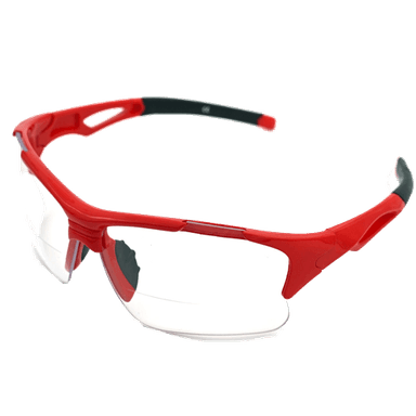
- Safety glasses
- Nitrile gloves
- Wheel chocks
- Floor jack (rated 3-ton minimum)
- Jack stands (rated 3-ton minimum)
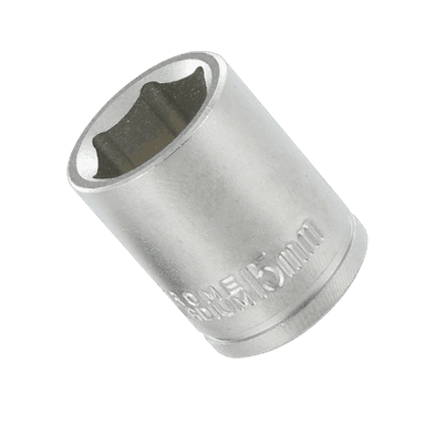
- 10mm socket
- 12mm socket
- 14mm socket
- 17mm socket
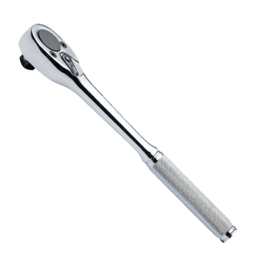
- Ratchet wrench 3/8-inch drive
- Breaker bar 3/8-inch drive
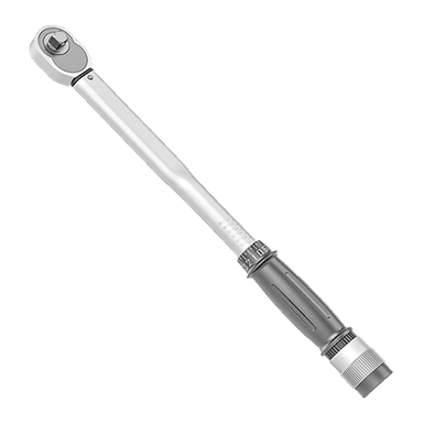
- Torque wrench 3/8-inch drive
- Serpentine belt tool (specialty)
- Trim clip removal tool
- Flathead screwdriver
- A/C manifold gauge set R-1234yf (specialty)
- A/C refrigerant recovery machine R-1234yf (specialty)
- A/C vacuum pump (specialty)
- Refrigerant scale (specialty)
- Digital thermometer
🔩 Required Parts
HowToo sells all the parts you need for this repair:
- A/C compressor assembly - Qty: 1
- A/C compressor line O-ring kit - Qty: 1
- PAG compressor oil for R-1234yf systems - Qty: As required by compressor instructions
- R-1234yf refrigerant - Qty: Use under-hood label specification
- Serpentine drive belt - Qty: 1
- A/C receiver/drier or desiccant service kit - Qty: 1
📋 Before You Begin
- Park your Altima on level ground, set the parking brake, and chock the rear wheels.
- Have the A/C refrigerant recovered using an R-1234yf refrigerant recovery machine. Recovery means safely removing and storing the refrigerant before opening the system.
- Open the hood and read the A/C charge label. Use that exact refrigerant type and charge amount during recharge.
- Disconnect the negative battery cable using a 10mm socket.
- Let the engine cool completely before working around the belt, pulleys, and compressor.
- If the old compressor failed internally and sent metal debris into the system, the condenser and expansion valve may also need replacement. Do not skip this check.
🔨 Step-by-Step Instructions
Follow these steps in order:
Step 1: Recover the A/C Refrigerant
- Use an A/C manifold gauge set R-1234yf and A/C refrigerant recovery machine R-1234yf to recover the refrigerant from the system.
- Connect the service hoses only to the matching R-1234yf service ports. The ports are different sizes to prevent mix-ups.
- Confirm both high-side and low-side gauges read 0 psi before opening any A/C line.
- Never loosen lines under pressure.
Step 2: Raise and Support the Front of the Vehicle
- Place wheel chocks behind the rear wheels.
- Use a floor jack rated 3-ton minimum to lift the front of your Altima at the front jacking point.
- Set the vehicle onto jack stands rated 3-ton minimum.
- Gently shake the vehicle to confirm it is stable before going underneath.
Step 3: Remove the Right Front Lower Splash Shield
- Use a trim clip removal tool to remove the plastic clips from the right front lower splash shield.
- Use a 10mm socket to remove any retaining bolts.
- Remove the shield and set it aside.
- Keep clips in a small cup.
Step 4: Remove the Serpentine Drive Belt
- Use a serpentine belt tool or breaker bar 3/8-inch drive on the belt tensioner.
- A belt tensioner is a spring-loaded pulley that keeps the belt tight.
- Rotate the tensioner to release belt tension, then slide the belt off the A/C compressor pulley.
- Slowly release the tensioner. Do not let it snap back.
- If replacing the belt, remove it fully and compare the new belt length and rib count before installation.
Step 5: Disconnect the Compressor Electrical Connector
- Use your fingers or a flathead screwdriver to release the locking tab on the compressor electrical connector.
- Pull the connector straight off. Do not pull on the wires.
- Move the harness aside so it will not be pinched during removal.
Step 6: Disconnect the A/C Lines from the Compressor
- Use a 10mm socket or 12mm socket to remove the A/C line retaining bolts at the compressor.
- Gently wiggle the suction and discharge lines free from the compressor ports.
- Suction line means the larger low-pressure line. Discharge line means the smaller high-pressure line.
- Immediately cap or cover the open lines with clean plugs or clean tape.
- Remove and discard the old O-rings from the line fittings.
Step 7: Remove the A/C Compressor Mounting Bolts
- Support the compressor with one hand.
- Use a 14mm socket and ratchet wrench 3/8-inch drive to remove the compressor mounting bolts.
- Lower the compressor out of the engine bay from underneath.
- Note the bolt locations so each bolt returns to the same position.
Step 8: Prepare the New Compressor
- Compare the new A/C compressor assembly to the old one. The pulley, connector, and line ports must match.
- Use the compressor supplier’s instructions to verify oil amount. Drain and measure oil from the old compressor if required.
- Add the correct amount of PAG compressor oil for R-1234yf systems if the new compressor is not pre-filled to the required amount.
- Turn the compressor clutch or hub by hand several rotations before installation to distribute oil inside.
- Wrong oil amount can ruin it.
Step 9: Install the New Compressor
- Position the new compressor onto the mounting bracket by hand.
- Start all mounting bolts by hand first to avoid cross-threading.
- Use a 14mm socket and torque wrench 3/8-inch drive to tighten the compressor mounting bolts to Torque to 25 Nm (18 ft-lbs).
Step 10: Install New A/C Line O-Rings
- Remove the protective caps from the compressor ports only when ready to connect the lines.
- Install new O-rings from the A/C compressor line O-ring kit onto the suction and discharge line fittings.
- Lightly coat each O-ring with clean PAG compressor oil for R-1234yf systems.
- Push the lines straight into the compressor ports.
- Use a 10mm socket or 12mm socket and torque wrench 3/8-inch drive to tighten the A/C line retaining bolts to Torque to 8 Nm (71 in-lbs).
Step 11: Reconnect the Electrical Connector
- Push the compressor electrical connector onto the compressor until the lock clicks.
- Use your hand to gently tug the connector and confirm it is locked.
Step 12: Install the Serpentine Drive Belt
- Route the belt around the pulleys using the belt routing label under the hood.
- Use the serpentine belt tool or breaker bar 3/8-inch drive to rotate the belt tensioner.
- Slide the belt over the final pulley, then slowly release the tensioner.
- Check every pulley groove to make sure the belt ribs are fully seated.
- One missed rib can shred the belt.
Step 13: Replace the Receiver/Drier or Desiccant
- Use the applicable 10mm socket, 12mm socket, or 14mm socket to access the receiver/drier or desiccant service location.
- The receiver/drier or desiccant absorbs moisture inside the A/C system.
- Install the new A/C receiver/drier or desiccant service kit following the part’s included orientation and sealing instructions.
- Use new O-rings and lightly coat them with clean PAG compressor oil for R-1234yf systems.
- Tighten small A/C line fasteners to Torque to 8 Nm (71 in-lbs) unless the part instructions specify otherwise.
Step 14: Reinstall the Splash Shield
- Position the right front lower splash shield back in place.
- Use a trim clip removal tool by hand to reinstall the plastic clips.
- Use a 10mm socket to reinstall the retaining bolts snugly.
Step 15: Evacuate the A/C System
- Use an A/C manifold gauge set R-1234yf and A/C vacuum pump to pull the system into vacuum.
- Run the vacuum pump for at least 30-45 minutes.
- Close the manifold valves and watch the gauges for 10-15 minutes.
- If vacuum drops, there is a leak that must be fixed before charging.
Step 16: Recharge the A/C System
- Use a refrigerant scale, A/C manifold gauge set R-1234yf, and the correct R-1234yf refrigerant.
- Charge by weight only. Use the exact amount printed on the under-hood A/C label.
- Reconnect the negative battery cable using a 10mm socket.
- Start the engine, set A/C to MAX COOL, blower high, and doors open.
- Finish charging through the low-side service port only.
Step 17: Check A/C Operation
- Use a digital thermometer in the center dash vent.
- Let the A/C run for several minutes at idle.
- Verify the compressor engages smoothly and the vents blow cold air.
- Use the A/C manifold gauge set R-1234yf to confirm pressures are stable and normal for the outside temperature.
✅ After Repair
- ✅ Check around the compressor, line fittings, and receiver/drier area for oily residue, which can indicate a refrigerant leak.
- ✅ Listen for abnormal belt noise, pulley wobble, clicking, or grinding.
- ✅ Confirm the serpentine belt is centered on every pulley.
- ✅ Test drive your Altima with the A/C on, then recheck vent temperature with a digital thermometer.
- ✅ If cooling is weak, do not add refrigerant blindly. Recheck charge weight, pressures, and leak status.
💰 DIY vs Shop Cost
Shop Cost: $1,100-$1,900 (parts + labor)
DIY Cost: $450-$900 (parts only, not including recovery/recharge equipment)
You Save: $400-$900 by doing it yourself!
Shop labor rates vary but typically run $100-$150/hour. This repair takes a shop approximately 3-5 hours.
🎯 Ready to get started?
HowToo makes it easy: same-day/2-day shipping on every part, plus all the tools and specialty tools you need! Check out the parts and tools sections below to add everything to your cart.
🔧 Altima - Rear Door Lock Actuator Replacement
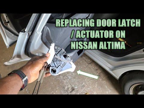
The rear door lock actuator is the small electric motor inside the rear door latch that locks and unlocks the door when you use the key fob or power lock switch. On your Altima, the actuator is serviced as part of the rear door latch/lock assembly, so the inner door panel and moisture barrier need to come off to access it.
Difficulty Level: Intermediate | Estimated Time: 1.5-2.5 hours
⚠️ Safety & Precautions
- ⚠️ Disconnect the negative battery cable before unplugging door electrical connectors.
- ⚠️ Keep the window fully raised while working inside the door.
- ⚠️ Door sheet metal edges can be sharp, so wear gloves.
- ⚠️ Do not tear the clear plastic moisture barrier; it prevents water leaks into the cabin.
- ⚠️ Support the door trim panel while unplugging connectors so wiring is not stretched.
🔧 Required Tools
You'll need the following tools for this repair:
- Safety glasses
- Mechanic gloves
- 10mm socket
- Ratchet wrench 1/4-inch drive
- Torque wrench 1/4-inch drive
- Phillips #2 screwdriver
- Flathead screwdriver
- Plastic trim removal tool
- Door panel clip removal tool
- Torx T30 screwdriver
- Needle-nose pliers
- Pick tool set
- Butyl tape roller
🔩 Required Parts
HowToo sells all the parts you need for this repair:
- Rear door lock actuator/latch assembly - Qty: 1
- Rear door trim panel clips - Qty: As needed
- Butyl sealing tape - Qty: 1 roll
📋 Before You Begin
- Park your Altima on level ground and turn the ignition off.
- Move the rear window fully up before disconnecting the battery.
- Open the rear door you are repairing and keep it open for the whole job.
- Disconnect the negative battery cable using a 10mm socket.
- Place a towel under the door to protect the painted sill and trim pieces.
🔨 Step-by-Step Instructions
Follow these steps in order:
Step 1: Remove the Inner Door Handle Trim
- Use a plastic trim removal tool to gently pry off the small trim cover behind the inner door handle.
- Use light pressure and work from the edge so the plastic tabs do not snap.
- Plastic tabs break when forced.
Step 2: Remove the Door Pull Trim and Screws
- Use a plastic trim removal tool to lift the cover inside the door pull handle area.
- Use a Phillips #2 screwdriver to remove the exposed screw behind the inner handle trim.
- Use a Phillips #2 screwdriver to remove the screw in the door pull area.
- Set the screws in a cup so they do not get lost.
Step 3: Release the Door Trim Panel Clips
- Use a door panel clip removal tool at the lower rear corner of the door panel.
- A door panel clip tool is a flat fork-shaped tool that pops plastic clips loose without tearing the panel.
- Work around the bottom and sides of the panel until all clips release.
- Lift the panel straight upward to unhook it from the window ledge.
Step 4: Disconnect Door Panel Wiring and Cable
- Support the door panel with one hand.
- Use a flathead screwdriver to press the release tabs on the window switch electrical connectors.
- Disconnect the door handle cable from the inner handle using needle-nose pliers.
- A cable end is the small metal ball or hook that sits in the handle lever.
- Set the door panel somewhere safe with the finished side facing up.
Step 5: Peel Back the Moisture Barrier
- Use a plastic trim removal tool to slowly separate the clear plastic moisture barrier from the black butyl adhesive.
- Butyl adhesive is a sticky rubber sealant that stays soft and reseals the door liner.
- Peel back only the rear half of the barrier to access the latch area.
- Do not cut the barrier unless absolutely necessary.
Step 6: Disconnect the Lock Rods and Cables
- Locate the rear door latch at the back edge of the door.
- Use a pick tool set to rotate the plastic retaining clips off the lock rods.
- Use needle-nose pliers to lift the rods out of their clips.
- Take a phone photo before removing anything so the rods go back in the same positions.
- Photos prevent mix-ups later.
Step 7: Disconnect the Actuator Electrical Connector
- Reach inside the door and locate the electrical connector on the latch/actuator assembly.
- Use a flathead screwdriver to press the connector lock tab if it is tight.
- Pull the connector straight off the actuator. Do not pull on the wires.
Step 8: Remove the Rear Door Latch Fasteners
- At the rear edge of the door, use a Torx T30 screwdriver to remove the latch mounting screws.
- Hold the latch assembly from inside the door while removing the last screw.
- Lower the latch/actuator assembly through the door opening.
Step 9: Install the New Latch/Actuator Assembly
- Place the new rear door lock actuator/latch assembly inside the door in the same orientation as the old unit.
- Start the latch screws by hand first to avoid cross-threading.
- Use a Torx T30 screwdriver and torque wrench 1/4-inch drive to tighten the latch screws to Torque to 7.8 Nm (69 in-lbs).
Step 10: Reconnect Rods, Cables, and Wiring
- Use needle-nose pliers to insert the rods back into the same latch levers.
- Use a pick tool set to rotate each plastic retainer clip fully closed around the rod.
- Reconnect the actuator electrical connector until it clicks.
- Confirm every rod moves freely and does not bind.
Step 11: Test the Lock Before Reassembly
- Reconnect the negative battery cable using a 10mm socket.
- Use the power lock switch to lock and unlock the door while the door is still open.
- Use a flathead screwdriver to manually click the latch closed, then pull the handle to release it.
- Do not close the door until you confirm the latch releases correctly.
- If the lock moves backward or the handle does not open the latch, recheck the rod positions.
Step 12: Reseal the Moisture Barrier
- Disconnect the negative battery cable again using a 10mm socket before final panel installation.
- Press the moisture barrier back into the original butyl adhesive.
- Use a butyl tape roller to seal the edges firmly.
- Add butyl sealing tape anywhere the original seal is torn, thin, or no longer sticky.
- A poor seal causes wet carpet.
Step 13: Reinstall the Door Trim Panel
- Reconnect the inner handle cable using needle-nose pliers.
- Reconnect the window switch connectors by hand until they click.
- Hang the top of the door panel over the window ledge.
- Align the panel clips with the door holes.
- Press around the panel edges by hand to snap the clips into place.
- Replace any broken rear door trim panel clips before final installation.
Step 14: Reinstall Screws and Trim Covers
- Use a Phillips #2 screwdriver to reinstall the screw in the door pull area.
- Use a Phillips #2 screwdriver to reinstall the screw behind the inner handle trim.
- Snap the trim covers back into place by hand.
- Reconnect the negative battery cable using a 10mm socket.
✅ After Repair
- ✅ Test the rear door lock using the key fob, driver door switch, and rear door lock knob.
- ✅ Open the door from both the inside and outside handles several times.
- ✅ Confirm the child safety lock is not accidentally switched on.
- ✅ Check that the window switch works and the door panel sits flush.
- ✅ Spray a light stream of water over the outside of the door glass area and check inside for leaks.
💰 DIY vs Shop Cost
Shop Cost: $300-$550 (parts + labor)
DIY Cost: $90-$220 (parts only)
You Save: $180-$330 by doing it yourself!
Shop labor rates vary but typically run $100-$150/hour. This repair takes a shop approximately 1-2 hours.
🎯 Ready to get started?
HowToo makes it easy: same-day/2-day shipping on every part, plus all the tools and specialty tools you need! Check out the parts and tools sections below to add everything to your cart.